
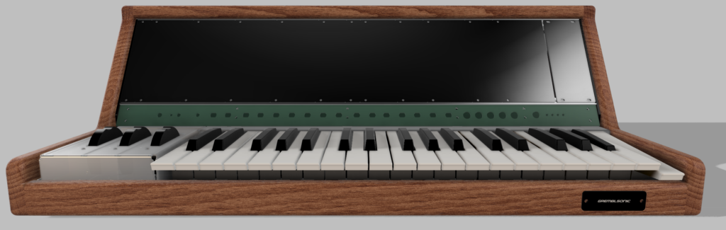
With the main modular audio chain assembled, and (almost) playable from a 37-key piano keybed, I recently turned my attention to designing an enclosure to hold all the components of the synth together.
What’s in a synth?
The playable components of the synth include a collection of 3U Eurorack modules, seated on a pair of 126HP rack rails, a 37-key Fatar piano keybed, and a set of wheel controls for pitch bend and modulation of the LFO or other signals. These needed to be pulled together into a single unified instrument rather than just spread out loosely on my workbench. (Not least because the keybed is not especially playable without being bolted down; pressing the keys while it’s freestanding causes the entire assembly to tip forward.)
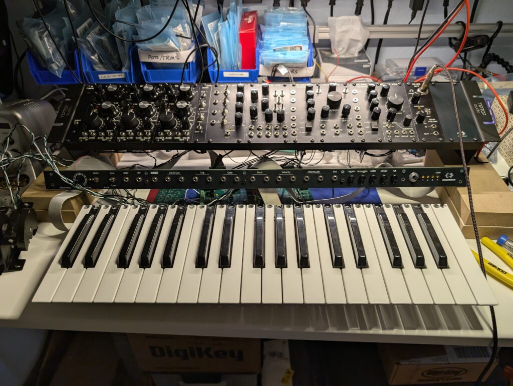
In addition to these main control systems, there was the power PCB I had also developed to hide in the case, as well as a “motherboard” PCB hosting an Arduino that was responsible for scanning the keybed and sending pitch CV info to the oscillators via a DAC, as well as handling MIDI I/O as well as other keyboard signals like velocity, aftertouch, etc.
I don’t have a fixed idea of where to route the velocity and aftertouch signals in the overall sound chain. While a lot of signals are pre-wired in semimodular fashion, I don’t plan to hardwire these into the VCA, for example. Instead, I developed the idea of a “dashboard”: a 1U full-row panel seated below the main modules which would have several jacks emitting pitch CV, aftertouch, velocity, and a few other signals managed by the motherboard which can be patched at will when playing the instrument. The dashboard would also have some utility buttons and switches for controlling the integrated synth instrument, managed by the motherboard.
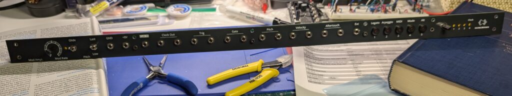
The dashboard itself is fabricated as two PCBs: one is “actually” a PCB, hosting the switches, pots and jacks, as well as some op amps needed for buffering and a few status LEDs. It connects to the motherboard via two 20-pin ribbon cables, one on each end. The instrument enclosure is built around the 126 HP rails (640mm, about 25″ wide) holding the modules, and the dashboard spans that entire width. The main PCB itself is 1″ high and just shy of the 25″ length. The front panel for the dashboard is slightly larger, and also fabricated out of FR4, with a layer of black solder mask providing the color to match the black module front panels, and white silkscreen labels for all the jacks and buttons. Most output signals are buffered and available through two jacks, so they can be wired to multiple CV inputs at once.
I had the dashboard fabricated by JLCPCB. They ended up charging me a $30 surcharge that I wasn’t entirely expecting to make PCBs > 600 mm wide, but even with that, it was still much cheaper than having this made out of aluminum and silkscreened elsewhere. (And alas, they can’t make aluminum PCBs in this width.) They also warned me that the extreme aspect ratio of > 10:1 length to width meant it was at risk of warping. I had planned ahead and designed several mounting holes along the dashboard to hold it down, so I acknowledged this risk before they built it. And indeed, the PCBs were not especially rigid at this length. If I were to redo these parts, I would probably opt for thicker 2mm FR4 rather than the standard 1.6mm thickness. That said: this will work.
Designing an enclosure
I worked up the cabinet design in Fusion 360. My CAD skills aren’t especially great, but I definitely learned a lot and improved over the course of this project. My plan was to use sheet metal for some of the structural components, especially the base, which would be the mounting platform for a number of closely-packed components. The top and sides of the case would be made of wood and a pair of narrow wooden rails would complete the rigid wooden frame. The metal structural panels, module rails, and dashboard would be fastened to the wooden structure across the front. The keyboard and wheel controls would be mounted on the metal base and would sit in the front of the cabinet.
Mounting all of these elements (including the PCBs) on the base would require some fairly precise positioning. Fortunately, laser cut sheet metal offers the precision necessary for a tight fit. I planned to take advantage of SendCutSend’s ability to precisely laser cut and bend sheet metal for the base. Given the close quarters, I also intended to take advantage of their ability to install press fit nuts, studs, and standoffs to facilitate blind assembly of some closely packed components.
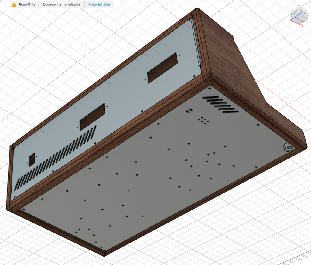
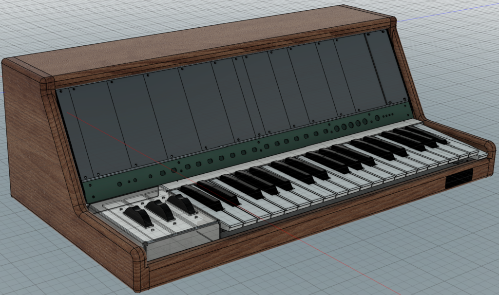
I also knew I would likely need to periodically rework interior elements of the synth, so I wanted the rear panel to be easy to remove. But how would I fasten it in place? I ended up opting for a row of five mounting screws along the bottom of the rear panel. To prevent the panel from “tipping forwards” into the case, I designed a bent sheet metal “backstop” to embed in the top of the case, with some press-fit studs providing some precise alignment:
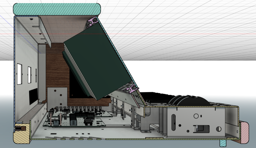
Section view of the case design
The rear panel would have the top and sides folded in for a finished external edge, and the studs mounted in the “backstop” along the top of the case would slot into some registration holes in the top edge of the panel. The studs wouldn’t be fixed to the rear panel with fasteners to help take the load, but between the screws at the bottom and a pair of metal “feet” I added to the rear panel to sit on the wooden rail, I hoped that was enough to make it sturdy. As it turns out, I didn’t fully appreciate exactly how light aluminum is even for a fairly big part. With the fabricated rear panel in hand, I think the “feet” are actually an unnecessary complication, and relying only on the mounting holes would have probably been fine.
In the section view above you can also see that I designed a sheet metal “guard” to fit over the back edge of the keyboard, and fastened to the base. Press fit studs extending from the back of the guard will affix to some bent flanges attached to the dashboard, which provide dashboard rigidity and fixturing it tightly behind the keyboard and wheel controls.
Choosing a vendor: Where do you get sheet metal parts fabricated?
The internet, of course.
More seriously: there are any number of independent metal shops who will quote you from a STEP file, but they will probably charge you much more than you want to spend. They are generally geared for production manufacturing and not aimed at hobbyists or tinkerers.
But there are also an increasing number of “instant quote” vendors online who offer less-expensive services by relying on automation. You can continually upload STEP files of your parts to their quote engine, and use their tools effectively as inline D4M checks for both manufacturing feasibility and cost optimization purposes. They all have some different trade-offs though:
- — Xometry will quote for basically any size part with any combo of secondary operations but they charge a lot even for simple parts, and they are an aggregator (like pcbway) who farms out the work to third party machine shops they don’t directly control. This made it feel like a gamble to try and work through them, so I didn’t order parts via this service.
- — SendCutSend is a budget-sensitive option aimed squarely at hobbyists. Their site, blog, and YouTube channel are full of tips to teach yourself sheet metal design, CAD, D4M, etc. They quote at qty 1 and their minimum process fees are crazy low, like $9. The only downside is they offer this cheaply because they are somewhat limited and very specific in the services they offer: no “advanced” bending operations like hemming; fixed bending die size per material; CNC cutting is restricted to XY-axis full-depth cuts, no blind drills, chamfers, or even tool changes; and somewhat frustrating min and max part sizes for finishing services. But they describe these limits and their design rules very clearly and precisely upfront, and offer great advice on how to get good parts out the other side. Their support team is very helpful (and fast!) over email, too. If you fit in the box of what they serve, they’re a fantastic resource for a hobbyist maker. Free shipping, too!
- — Oshcut is another vendor positioning themselves to compete with SendCutSend for the hobby market. They also have a fast and easy-to-use instant quote tool, which even shows in a 3D rendering why some bend operations would not be possible to make with their equipment. They lack some services that SendCutSend has (e.g. PEM hardware insertion, or any CNC plastic materials) but make up for that with wider size tolerances on various secondary processes like powder coating, and some interesting complementary services like laser cut metal tube.
- — PartsBadger is another one that’s been advertising to me, but their quoting tool flips from “instant quote” to “manual quote” if you want more than three bends, so even a simple four-sided box requires that you go back and forth with a person, which is hard when I’m very clumsily iterating on my design.
- Finally, Protocase can also do a lot and focuses on a quality finished look with engraving and silkscreening for panel labels, but they are a more premium service and they charge like it.
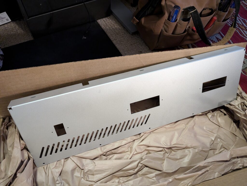
One constraint of SendCutSend’s process limits is that they don’t offer metal finishing on any parts more than 23″ wide (before any bending), and the rear panel would need to be over that limit. While I eventually decided I was OK with the bottom panel being unfinished, I wanted something cleaner looking (and smoother to the touch) for the rear panel. I wound up having Oshcut fabricate this component, as they were able to media blast it for a very reasonable fee. Unfortunately, Oshcut won’t do hardware insertion, which is a shame because their ability to media blast or powder coat large parts is a win over SendCutSend’s more-limited finishing services–although they charge a hefty setup fee for larger-part powder coating.
My initial vision involved both of those larger parts being powder coated to match the front-facing elements, but I eventually decided this wasn’t possible on a reasonable budget. I also looked into quotes from independent local powder coating shops for this, but they all quoted minimum prices of several hundred dollars per part, despite their web sites listing much lower fees. (Admittedly, these indie shops may have set up their web sites sometime during the Obama administration and I don’t think they updated them rigorously.)
In any case, if you’re thinking about designing a bent sheet metal part, you should read through the process limits of each vendor and have one in mind before you start. Building a complex assembly may mean making tradeoffs regarding which services can be applied in combination to each part you design.
How much does metal fabrication cost?
Maybe less than you would think! It does pay to shop around. The various vendors listed in the previous detail segment have somewhat different pricing models. SendCutSend doesn’t have setup fees per se, but they do have (very low) minimum per-operation fees (e.g., for tapping, anodizing, etc.) you need to hit or else they’ll mark up the smallest orders you might submit. They offer fairly steep discounts even at qty 2 so if you can design an assembly out of four identical smaller parts that fit together, that could be much cheaper than one big part. If you are getting a few parts made at once, you’ll likely be over these minimum price hurdles. Free shipping, too!
Oshcut explicitly charges a setup fee which might be anywhere from $20 to $80 depending on your order. They usually have slightly lower unit costs than SendCutSend, so there’s a crossover point where this will be cheaper. The setup fees for some operations (like powder coating) were fairly surprising (e.g., more than the cost of the part). Unlike SendCutSend, they also charge for shipping, which might be a surprisingly high surcharge for a small or modestly-sized order. A $20 shipping fee turned an amazing deal on an $80 part into just a “pretty good” deal to get the part made and to my door for $100.
On the whole, though, this was not nothing, but I also thought it reasonable compared to the costs sunk into other aspects of the synth project: the biggest parts (the bottom and rear panels) cost about $100 each, and all the custom metalwork together (across multiple part designs, vendors, and orders) was about $500.
Parts!
The metal parts were mostly fabricated by SendCutSend, with the exception of the rear panel discussed above. In addition to the rear and bottom panels, I needed:
- Two mounting flanges for the rack rails and dashboard
- The backstop flange for aligning the rear panel
- Some custom mounting flanges for the dashboard
- The keyboard guard that wrapped the “raw” rear side of the keybed
- The mounting frame for the left-hand wheel controls, as well as the wheels and their own hardware
After a wait of about two weeks (pretty fast, for custom work!) the parts came back from the fabricators:
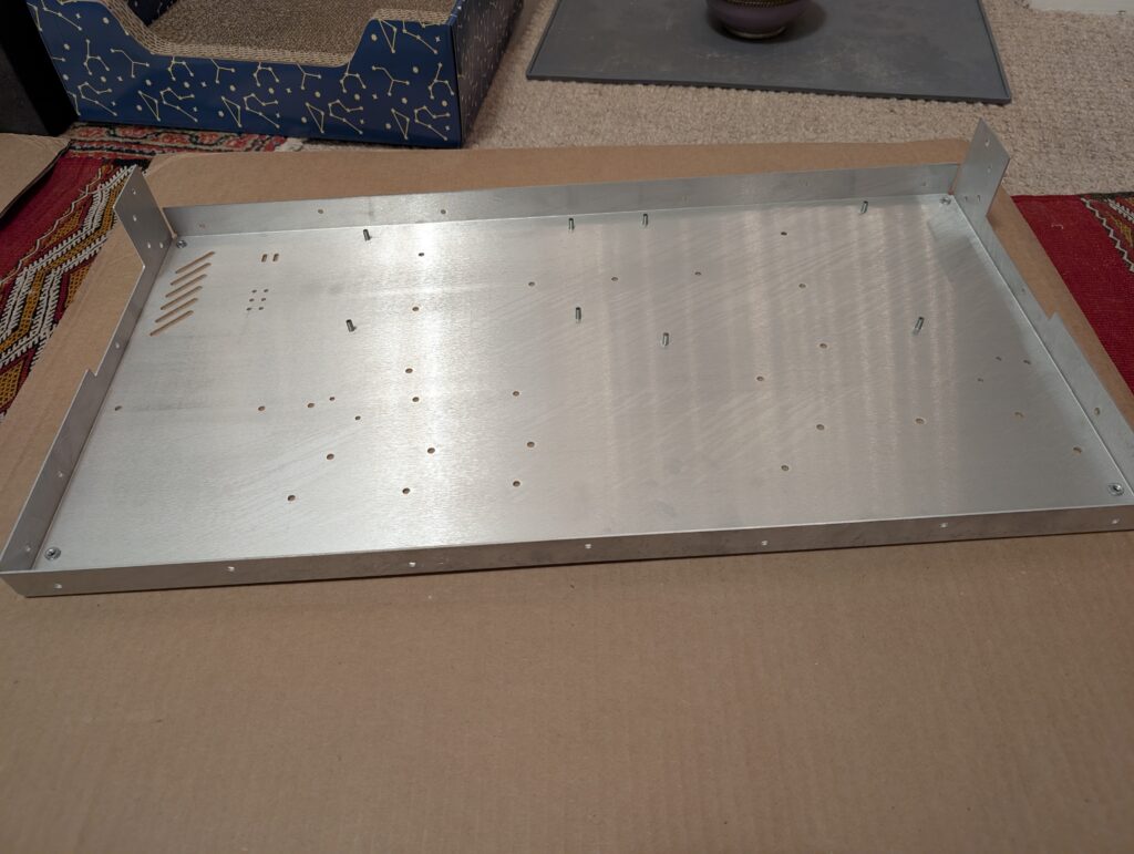
I was actually somewhat concerned that the base would not be rigid enough. The parts were all fabricated from 1.6mm thick 5052 H32 aluminum. The sides were folded up an inch or more, but the overall area was 14×25″ which is a lot of room for the sheet metal to warp. So I also had a half dozen 1″x6″ bars of 1/8″ thick 6061 aluminum cut out with holes at regular intervals, which I finished with an M4 hand tap. I applied five of these ribs at some intervals on the base that I hoped would improve the rigidity and coplanarity of the whole unit:
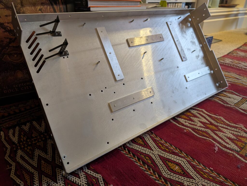
The stiffening ribs did make a decent improvement in the rigidity of the base. Per-part cost goes down fast if you order in multiples, and laser cut metal without bending or finishing is already very reasonable, so this upgrade didn’t add too much to the fab cost for the base. This now felt like a reliable foundation for the instrument. I also hope that once I install the keybed to its own ten mounting holes along the front of the base, that will further tighten up the total system. In the meantime, with the holes for the stiffening ribs now occupied by the screws that affix the ribs to the base, the logic behind the remaining hole pattern starts to look much clearer as well.
As excited as I am to put everything else together, further assembly requires the wooden parts as well. Not trusting my own crude woodworking skills (nor having the tools or space to do the work right) I also sent out for those parts to be CNC cut by a local shop. I’m still waiting on those parts, so assembly is paused for a bit from here. Next time I’ll follow up with the wood assembly — stay tuned…
Hi, I really enjoyed reading your Custom Synth Enclosure write-up. It’s a great blend of practical design and thoughtful execution. I’m Emily from PCBWay, and we’d love to support your projects with free PCB or PCBA services. If you’re open to it, a brief review of your experience would be much appreciated. Would you be interested in collaborating?