
I am building a solar-powered outdoor art project and built this simple A-frame to hold my solar panels. In case this is useful to others, here are the steps to build one for yourself. This project can be accomplished by one person with about 6–8 hours of work.
The Bill of Materials:
Parts:
- HQST-100D-SS solar panels (x2)
- 2″x4″x8′ dimensional lumber (x6)
- A21 Simpson Strong-Tie angle brace (x15, or x11 if using only two tabs/side/solar panel)
- M4x12mm rounded head machine bolts (x12)
- M4 locking split washers, flat washers, and nuts (x12)
- #9 1.5″ wood screws (1 lb. box is plenty)
- #9 or #10 2.5″ or 3″ wood screws (1 lb. box is plenty)
- Varnish, paint, or other sealant + appropriate thinner (optional but recommended)
Tools:
- Drill; 5/64″ (wood), 3/16″ (metal), & 9/16″ (wood) drill bits, and screwdriver bit compatible with the heads on your wood screws
- Allen key sized for M4 bolts (assuming internal hex drive head) or other small screwdriver as appropriate
- Plyers or small open socket wrench or slip wrench
- Circular saw; blade with 24+ teeth
- Speed square
- Measuring tape
- Speed clamp (4″ or bigger)
- 80-grit and 120-grit sandpaper
- Paintbrush (foam for varnish, hair for paint)
- Pencil
- Some extra wooden blocks to keep things off the ground (cut a spare 2×4 into 1–2′ lengths)
Building it:
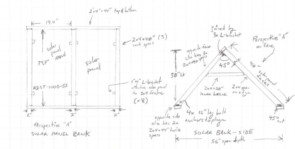
Reference Diagram:
To start with, here are the plans I drew for myself:
Adjustments:
For starters, you can use any solar panels as long as they have a metal frame with mounting holes on the back (or enough space for you to drill some holes). These solar panels were loaned to me by a friend, so that’s what I based the dimensions on. If you have different solar panels, you can scale this design to match them.
- Measure the width of the panels; 2×4’s are 1.5″ wide so add 4.5″ to two times the width and that gives you the minimum length for your horizontal spars. If you want to add ground anchors, add another 3–4″ to the horizontal spar length. (You only need to add that 3″ to the two footer spars, although I cut all four horizontal spars to the same length, leaving some “handles” at the top. My blueprint above shows 44″ horizontal spars because I added the extra overhang height after drawing it; also because making equal-size 48″ spars from 8′ lumber requires only one cut.)
- Measure the height of the panels. Your vertical spars need to be at least this long plus a little longer so that the panel doesn’t overhang the miter cut at the bottom of the vertical spar where it joins to the horizontal footer spar. The deeper the depth of the panels, the more you need. (Add at least 1.5x the depth.) The “worst case” is 3.5″ because we’ll be making a 45 degree (3.5″ x 3.5″) miter cut at the bottom of each vertical spar; so panel height + 3.5″ is totally safe but that will leave a little gap at the bottom between the panel and the footer spar. My blueprint above shows 40″ vertical spars but I actually cut mine to 41″ instead to account for this.
- You can also, of course, scale this to hold more than two solar panels (although at a certain point it starts to get heavy) by using longer horizontal spars. 2×4 lumber is readily available in lengths up to 12′ or 16′ at your local hardware/construction store.
- The solar panels in question have two oval mounting holes on each side. If the holes are slightly larger than the M4 bolts that pass snugly through the A21 angle braces, that’s great. (A washer underneath will make it secure.) If the panel mounting holes are smaller, scale down to M3 and get extra washers to go on the top as well as bottom of each bolt.
- My drawing above shows 8 angle brackets for mounting; there was actually a 3rd hole added to the side of each panel, so I actually used 12 angle braces. Go for 8 or 12 depending on how windy the area is you plan to mount this. Remember to design for the biggest windstorm you get each year, not the average.
Step 1: Cut the lumber to size
- Use the circular saw to cut two 2×4’s in half, giving you four 48″ horizontal spars. Two of these will be “header” spars (at the top) and two “footer” spars.
- If you want the overhanging handles shown in the photo at the top, leave them all 48″. Otherwise, slice the header spars down by 4″ to give yourself two 44″ header spars and two 48″ footer spars.
- Use the circular saw to cut three more 2×4’s into 41″ lengths for your vertical spars.
- I set the 2×4 being cut on some short lengths of 2×4 laid horizontally on the ground to keep the saw above the ground and enable me to clamp my speed square to the lumber next to the circular saw’s shoe, to help drive the saw across the lumber at a straight, perpendicular angle.
Step 2: Miter cut the vertical spars
To give the A-frame its 45-degree shape, we need to (miter) cut a 45-degree angle into the bottom of each vertical spar.
Dimensional lumber often has considerable imperfections in it. Pick the ugliest corner of each vertical spar as the one to slice off.
The speed square can help with this in two ways:
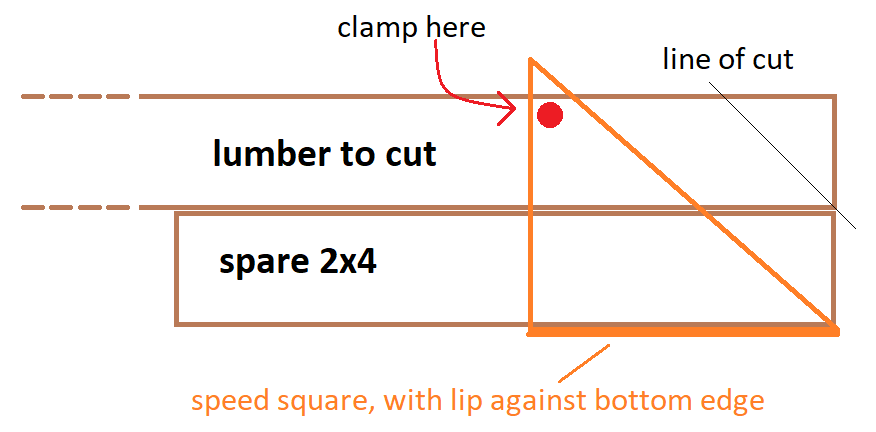
- Use its diagonal edge to draw a line running 45 degrees across the wider (3.5″) face of the wood from one edge to 3.5″ in on the other side.
- Again, clamp the speed square to the lumber, this time with the diagonal edge guiding the shoe of the saw. The width of the shoe makes it hard to do this with one 2×4 (you need to start the cut well before the shoe will make contact with the speed square), so I laid a second 2×4 next to the first, snugged the lip of the speed square against this bonus 2×4, and clamped the opposite corner to the 2×4 being cut, like so:
Step 3: Make the knee braces
- Cut two 20″ lengths from your remaining 2×4.
- Miter cut both ends of each knee brace so they are trapezoids with a 20″ side, and a ~16.5″ side.
- The exact size of the knee brace is unimportant, although if it’s too short it won’t give good bracing power. But +/- 2″ is ok. Even longer is also fine.
You are now left with the following lumber components:
- 6x 41″ vertical spars with one end miter cut 45 degrees
- 2x 48″ horizontal footer spars
- 2x 44″ or 48″ horizontal header spars
- 2x 20″ knee braces, miter cut on both sides
If they all look good, you can put away the saw at this point.
Step 4: Drill through-holes for mounting bolts
Measure 1″ in from each end of the two bottom spars and use the 9/16″ drill bit to drill a hole in the center of the spar’s 3.5″ face at that point. You can now use a 1/2″ bolt & washer to securely anchor this into the ground.
Step 5: Sanding
Everyone’s favorite part. I sanded mine with 80 grit sandpaper on all faces and edges to get rid of the splinters. If you’re going to paint or varnish, do a second pass with 120 grit. Get the inside of the anchor mounting holes too.
Step 6: Seal
My project has a very temporary design lifetime in a very dry place, so I skipped this step. But if your solar panels will live outside (as they probably should), in a place where it ever rains, you should do this. After prepping with 120 grit sandpaper, paint or seal with two coats.
Leave overnight to dry.
Step 7: Attach hardware to solar panels
This is the last step you can do on day 1, as you’ll need to wait for your sealant to dry/cure before proceeding to the next step.
- Lay the solar panels face down on the ground (set them on top of two or three horizontal spars to keep them from getting scratched). Take the A21 angle brackets and align them so that one of the holes in each angle bracket is over a mounting hole in the solar panel, with the other side facing out and pointing up toward you, aligned flush with the edge of the solar panel; attach with a bolt going through the A21, the panel, a flat washer, a lock washer, and a nut underneath.
- I held the nuts in place with my fingers and tightened with an Allen key. On one or two I used plyers to help hold the nuts at an awkward angle, but I mostly just got these “finger tight snug” so the lock washers engaged, rather than really cranking down.
- My solar panels had a 3rd hole drilled in the side of each frame so I used a total of six mounting tabs per panel. If you live in a place that’s less windy, you can probably get away without this. If you want the 3rd bracket on each side, use the 3/16″ drill bit to drill these holes.
If you haven’t stopped on day 1 yet, stop here and resume this tomorrow.
Step 8: Attach vertical spars
Lay the vertical spars down next to the sides of the solar panels, longer edge down, with the miter-cut ends at the bottom of the solar panels. Align them so that all the miter cut end points stick out aligned evenly with one another, and the depth of the solar panels does not overhang the miter cut (which will be flush against the footer spar).
Use a pencil to mark where the angle brackets make contact with the 2×4’s; drill a 5/64″ pilot hole at each such point, and use #9 1.5″ screws to attach the angle brackets to the 2x4s. You should now have something like this:
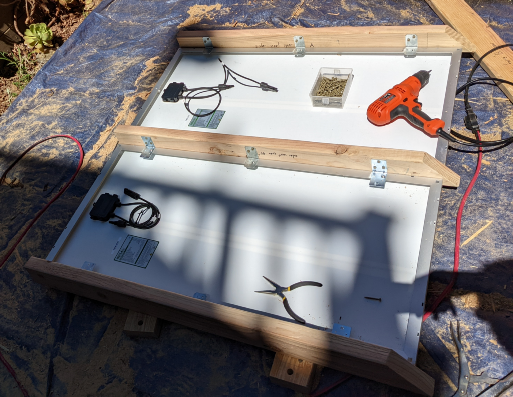
(There are a mix of angle brackets employed in this photo because of what I had on hand, but you can just use the smaller A21’s like you see in the top row.)
Step 9: Attach horizontal spars
Attach the header spar to the top of the three vertical spars with the longer (2.5″+) screws. Drill at least two screws into the end grain of each vertical spar.
Then repeat with the footer spar, making sure it is evenly centered and there is clearance around each anchor mounting hole. I drilled in from the bottom of the footer spar, into the end grain of the bottom of each vertical spar. You could flip the assembly over and do it from the other side though.
Finally, attach three angle brackets to the header spar along where it meets each vertical spar, so the top corner of the bracket is flush with the edge of the header spar. (I had one screw in the header spar and one in the vertical spar.)
Step 10: Build the other side
Lay out your three vertical spars for the “back” frame with the same spacing as on the first side. Screw them into the header spar, and then the footer spar. You’ll want the vertical spars on the back frame to align with those on the front so the attachment points line up.
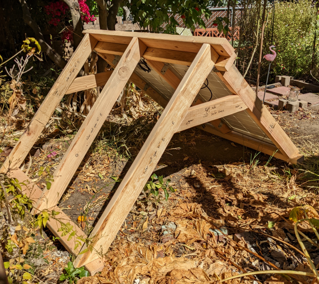
Step 11: Attach both sides
Leave the solar panel side face-down on the ground, and stand up the empty side next to it to make a right angle. The three angle brackets on the front side should line up with the vertical spars of the back side. Screw them together.
Finally, fit a knee brace into each end and screw it in place, at least two screws per end. (Drill perpendicular to the grain of the wood on the knee brace, going into the associated vertical spar at a 45 degree angle.)
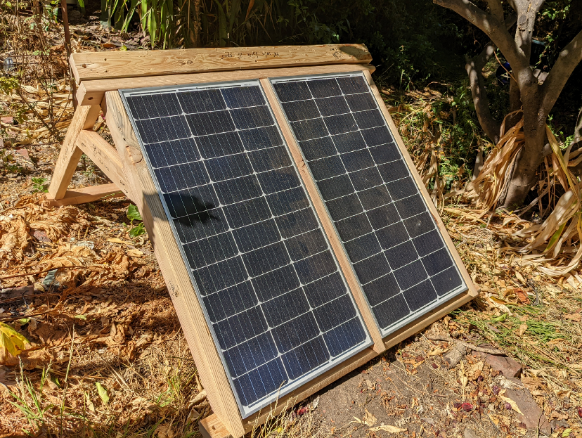
The finished product
You now hopefully have something that looks like this:
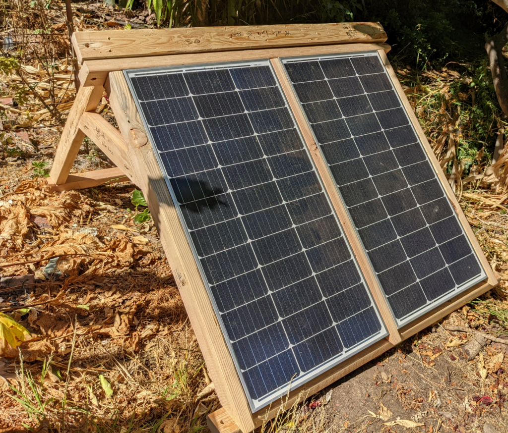
Now you can go wire it up to your charge controller and electrical assembly.
If you want to secure it to the ground, you can use 1/2″ lag bolts (with a washer) through the holes in the 4 bottom corners to attach it (e.g., into a cement anchor dug into the ground).