
Over the past year I’ve gotten into building modular synth components. There’s a lot more to share on that front; I’ve put together several modules and have a plan for several more to go into an integrated system. The relative complexity means there’s a lot to write about, though, which has made me keep putting it off…
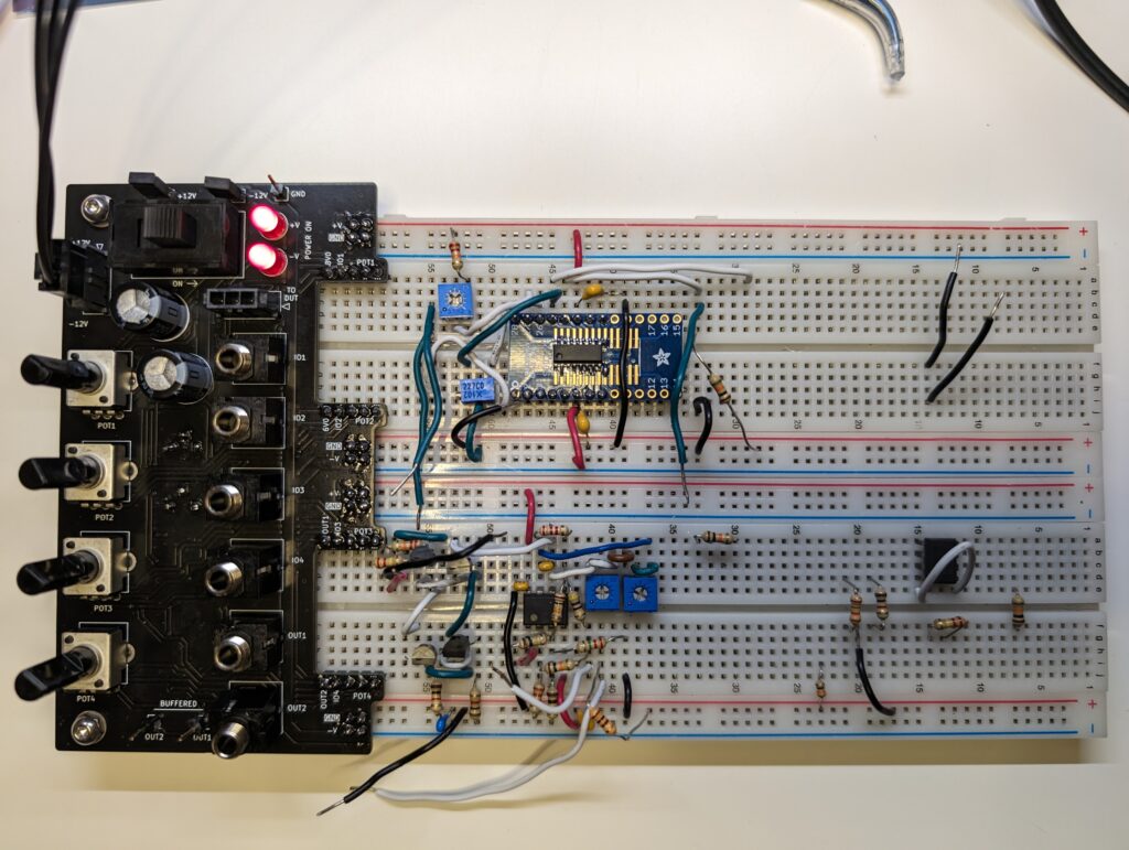
In the meantime, I completed a smaller project this weekend—a breakout board that makes it easier to develop audio circuitry on a breadboard:
This should hopefully make it faster and easier to prototype circuits. The basic features include:
- +/-12V power and GND sent to the rails of the breadboards via header pins.
- A power switch, and LEDs indicating power availability.
- Jumpers that selectively enable the +12 and -12V power busses, and can be used to insert an ammeter in series with either power bus.
- A power “output” jack to enable a synth module being tested to be powered through this breakout (with the switch and ammeter jumpers in series).
- Four potentiometers (two 100KOhm, two 10KOhm) with all three pins of each brought out to the breadboard.
- Four general-purpose 3.5mm phone jacks with tips brought out to the breadboard. (Sleeves are grounded.)
- +6.000V and +8.000V reference voltage pins.
- Two output 3.5mm phone jacks, which output the buffered voltage from two specific pins on the breadboard. Header pins make it easy to attach an oscilloscope to either buffered signal as well.
- Leveling feet on the “outboard” side of the PCBA so it is nicely supported as it overhangs the breadboard by a few inches.
The +6V and +8V reference voltages are created from Zener diodes buffered by one element each of a TL074H op-amp. Trim pots on the underside of the board enable these voltages to be mV-precise.
The other two elements of the TL074H are used to buffer the signal for the two “output” jacks. Between that and the pots, now it should be easy to plug this into a small speaker or headphones to listen to what’s going on at any point in a circuit.
Interacting with other modules has always been a pain, since integrating a breakout from a mono T/S cable (plugged into a synth module) into the breadboard is clumsy at best. Good potentiometers with nicely-sized shafts do not have pins that fit easily into a breadboard; so it’s either bend one of those, or use a trimpot and an adjustment tool. This should make that a lot less painful!
Even for standalone module development, or circuits that can work on the output of a function generator, the voltage references and pots will make it a much more pleasant (and hopefully faster) experience to prototype circuits.