
My next adventure in audio hacking involved working with the LM13700 OTA. This is an operational transconductance amplifier; like a regular op-amp, it has differential input and amplifies the difference to the output — but unlike a regular op-amp, this amplifies current rather than voltage. Moreover, it’s a three-terminal device: it has the usual inverting and noninverting inputs, as well as an “amp bias input,” called Iabc. The more current sent to Iabc (though not too much: max allowed is 2mA!), the stronger the amplification. I was able to see generally how this pin worked by using a pot between Vcc and Iabc, but that was a pain to measure and control. A precision current source like you’d find in an SMU would be very helpful. But an SMU costs an arm and a leg… my needs were not so great. Could I make what I needed without breaking the bank?
Source-Measure Units
Even a modest hobbyist in electronics typically has two devices available to them: an adjustable benchtop power supply, and a multimeter. The power supply is a voltage source. Dial in the voltage you want it to produce, connect to your circuit, and depending on the impedance of the circuit, the appropriate amount of current will flow. If you want to adjust that current, you need to work backwards to what the right voltage is. Moreover, the control isn’t super precise: a cheap supply is controlled in 100mV steps, and a better supply will let you control it in 10mV steps.
If you want to send a specific, adjustable amount of current into a circuit, that’s trickier. The device most commonly used for this is called a Source-Measure Unit, or SMU. Keithley makes a well-regarded one, the Keithley 2400. This device can force its output leads to a programmed positive or negative voltage or a programmed positive or negative current, with incredible precision. It can also measure voltage or current at the output to a ridiculous degree of precision, over a range of 100V or more. It also costs $5,000 just for the base model. Even an ancient used SMU from circa 1990 like a Keithley 236 costs over $1k on eBay — and the rack-mount form factor wouldn’t be especially welcome either.
You can do some pretty cool things with an SMU, though; by precisely driving current into the base and collector of a BJT, or precisely controlling the gate and drain voltages of a MOSFET, you can characterize the device and reproduce its curve family as seen on the datasheet. SMUs generally have programmable modes where they can step through the current setpoints and take measurements to produce these graphs. That’s neat, but also completely overkill for me.
What I need:
- Control a current source driving 100nA to 10mA
- “Reasonably high” precision: specify current level in 100nA increments up to 10µA, and higher current in 1µA increments
- “Reasonably high” accuracy: ideally 0.5%, but 1% would suffice. But the 0.05% accuracy and 100pA step increment of a Keithley 236 would be drastic overkill.
- Load current regulation as the load varies by 5–8 volts, at up to 20 kHz bandwidth.
- My modular audio devices all run on ±12V, so voltage needs enough headroom to support operation to the rails of the DUT, with compliance at least up to 2mA
Other things I’d like:
- Bipolar / four quadrant operation: sink the same range of current as it can source, and source/sink into either positive or negative DUT voltage
- The “Basic SMU” capability to measure voltage while sourcing/sinking current
- I already have a 6.5 digit multimeter I can use for precise measurement, so it doesn’t need to be incredibly precise, but a basic 3.5 digit capability to avoid an unnecessary spiderweb of test leads would make life more convenient
- Other simple calculations that can be backed out of knowing both current and voltage (power, resistance…)
- Physical buttons / knobs for controls
- A bright / backlit screen that’s easy to read in lower light
Controlling current
I started out by building and playing around with a Wilson current mirror on a breadboard. Even made of four unmatched BC547’s, this was actually a reasonably stable current sink. Using an op-amp with a potentiometer in the feedback loop, I could convert that sink into a true current source (positive current out); setting the current mirror’s input to 100µA with a resistor and using a large pot to amplify the current up or down was pretty stable up to about 1mA, but this has terrible PSRR, very sensitive to fluctuations in the power rail. Above 1mA, as things got hotter, the current would continue to creep up. Interestingly, adding a second smaller pot (to give myself “coarse” and “fine” adjustment) caused that temperature creep to stop in its tracks. Whether I got lucky with the particular pair of pots or not, they had almost precisely offsetting tempcos! Neat.
A helpful person on the eevblog forum (Kleinstein) then pointed me to the HP 34401A DMM’s service manual, to look at the internal current source used for resistance measurements, as it would be more stable and precise:
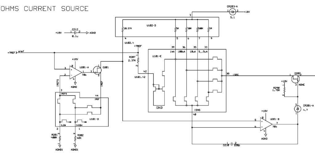
This somewhat-stylized schematic took a few evenings of staring at it to decipher what I was looking at. I had interpreted the various “square waves” in the diagram as BJT transistors; so I thought the IREFS section in the lower left was actually some sort of differential amplifier. These are really better just thought of as “switches,” controlled from elsewhere in the device. The two different IREFS just switch between a low- and high-range current, so it’s ok to just simplify to using a single resistor connected to the inverting input of U-201A and the JFET Q201. The JFETs (and biasing Zeners) can also be exchanged for MOSFETs. I eventually was able to understand the main “trick”, figure out what similar function I needed, and adapt it into a circuit like this:
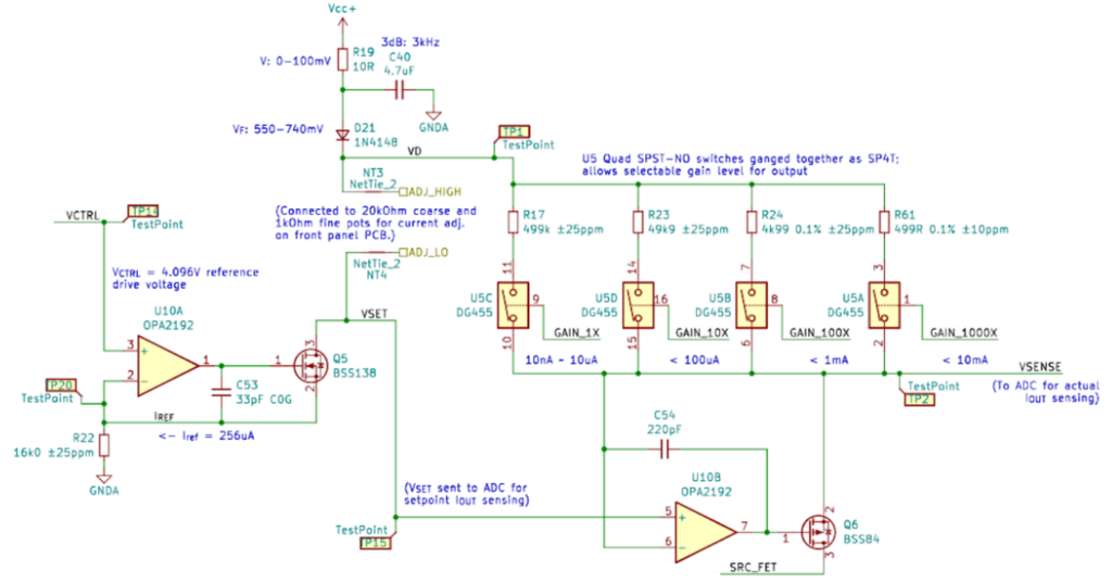
- VCTRL is a fixed voltage that biases U10A
- A single 16k0 resistor below U10A instead of high / low range resistors. If VCTRL is 4.096V (provided by a reference voltage, not shown), then the 16k resistor means a reference current of 256µA would always flow through Q5.
- The 34401A had four fixed “upper” resistors that would be switched on one at a time to feed U201-A. I used a variable pot (RV1, attached between ADJ_HIGH and ADJ_LO) to set the output current. The constant 256µA current would flow through the pot, and let the pot precisely control a voltage (VSET), fed to the non-inverting input of U10B.
- U10B will adjust the gate of a BSS84 P-type MOSFET (Q6) to make its inverting input equal to the VSET voltage. A resistor from Vcc to the source of Q6 would convert voltage to current. No current flows into the op amp, so all current from the resistor flows to Q6. As the gate voltage changes, Q6 lets more or less current out from Vcc to SRC_FET (the output).
- I could also use some analog switches to choose different output gain levels for the current set resistor.
- The OPA192 is a pretty incredible op amp with ±5 µV typical offset voltage and virtually no bias current (5 pA typical), and rail-to-rail input and output. Well, almost rail-to-rail output; like most R2R op amps, its reach is still a few mV shy of the rail itself. Adding a diode drop from Vcc means its always operating in a compliant range though, even at low current, with plenty of headroom above the 12V typical range for DUT voltage. An RC low-pass filter on Vcc helps keeps the PSRR of this device higher.
The elegant part of this design is how the math works out:
- The 256µA Iref reference current is entirely set by VCTRL and the 16k resistor R22.
- VSET is therefore equal to Vcc – RV1 * Iref. [For simplicity, combining the coarse/fine potentiometers into a single “RV1” pot, and ignoring the LP filter and diode, calling “VD” Vcc, here. This doesn’t change the math.]
- The noninverting input of U10B is equal to VSET.
- No current flows into or out of any op amp input, and the op amp inputs have equal voltage.
- The inverting input of U10B is therefore also at VSET. As is the source of Q6.
- Op amp feedback means a current must flow from Vcc and through the selected gain resistor such that Vcc – Iout * Rgain = VSET.
- All of that current must flow through Q6 since none can flow into the op amp, or back through Q6’s gate.
- After working through the math and simplifying the resulting equation, Vcc drops out of both sides.
- Therefore, Iout = (RV1 * VCTRL) / (R22 * Rgain).
This control setup is completely independent of the supply voltage, and Q6 will cause its own VDS to change as needed to cause exactly this much current to flow into the load.
The gain resistors chosen offer four ranges that the control knob(s) can operate over:
- up to 10µA
- up to 100µA
- up to 1mA
- up to 10mA
This is more stable than the original prototype circuit, and even when mocked up on a breadboard with inexpensive TL074s and 5% resistors with unimpressive tempcos, has excellent thermal stability up to 8mA in free air.
With ideal potentiometers, the four current ranges all technically go down to 0, but residual resistance in the pots will mean there’s always some voltage drop from Vcc, so there is always some minimal “on” current. I selected the Bourns PDB12 potentiometer (20k for coarse, 1k for fine) because the 10 ohm guaranteed max residual resistance is the lowest value I could find in a control panel pot. (On a 20k pot, that’s 0.05%!)
I also added a four-transistor current mirror made of two BCM847DS matched NPN pairs, so that an analog DPST switch can divert the “sourced” current into the servo side of the mirror, and with the output lead of this device diverted into the other side of the mirror, the instrument is converted into a current sink. A toggle switch on the front panel lets the user choose the current polarity.
That’s the circuit, right there. Everything else, as they say, is commentary.
Measurement
I reached for the Adafruit Feather M4 Express Arduino for the MCU. This Cortex-M4-based, SAMD51-powered device has plenty of RAM and program memory, a decent number of GPIO pins in a small footprint, 120 MHz, and two independent ADCs.
I use the TI REF35250 as a precise 2.500V (±1mV) analog reference for the ADC to measure against. I picked this mostly due to the high PSRR; the default ADC reference on the Cortex-M4 is the 3.3V output of its integrated LDO, which has some ripple.
I used some more low-offset op amps to measure the currents / voltages. A circuit very similar to the BSS84-based circuit above measures VSENSE and converts its output to another (smaller!) current, which when passed through a fixed precision resistor to GND, lets an op amp measure a voltage in the range acceptable to the ADC.
For “SMU” capability, to allow the instrument to measure voltage at the DUT, the output lead is also connected to another OPA192 in voltage follower configuration (which given the low Ib and Vos, will have basically no effect on the output current or voltage); the output of this sensor is passed through a voltage divider to bring it into the voltage range acceptable to the ADC. This was added somewhat late in the game; to avoid adding further precision range resistors and analog switches, I only use a single scaling resistor to bring the |0..15V| input range down to the 2.5V max ADC input voltage. This won’t be super precise but should add a somewhat useful secondary function.
Stargirl Flowers wrote a great blog post on using the ADC on the SAMD21, which is very similar to the SAMD51. She also covers a very useful technique for piecewise linear interpolation as a calibration mechanism for the ADC, which I was able to implement. (Though while the math is easy, actually creating an interface for measuring and entering the calibration data wound up taking almost 1/4 of the total lines of code in the project!)
Mechanical design
I chose a Hammond enclosure to build this into: 8×4″ front panel, 8″ depth (model #1458VD4). Hammond advertises that the removable end panels are “easily machined” but as I lack a machine room, or even a drill press (or silk-screening capability for labeling), that’s not really an option for me.
I need a front panel with a number of cutouts and other work:
- A large rectangular cutout for a 2×16 character OLED display (by Newhaven Devices)
- Rectangular cutouts for four buttons
- A circular hole for a toggle switch to poke through
- Two more holes for potentiometer knob stems
- 3.2mm holes for several indicator LEDs
- Holes for the banana jacks
- Silkscreen for labeling buttons and indicators, scales drawn around the knobs, and (of course) some swank branding.
I’ve used FrontPanelExpress for some small panels, but that would be pretty costly for this (probably about $90). Instead, I used a trick shared on the modwiggler Music Tech DIY forum: have JLCPCB fabricate an aluminum PCB (1.6mm), with an empty copper layer. The aluminum PCB will have a white primer layer on it, and you can have them use black solder mask. Instead of using white silkscreen (which will have ~okay resolution), put the text and graphics in the solder mask layer (which removes the solder mask) and exposing the white primer. The mask layer has registration accuracy down to about 0.003 mm, so this produces incredibly sharp detail. For $37 I got five of these (the minimum order); the unit cost of $7.40 is absolutely rock bottom, and even at $37 for one, it’s still an incredible deal.
Here’s a photo of a test fit in the Hammond enclosure:
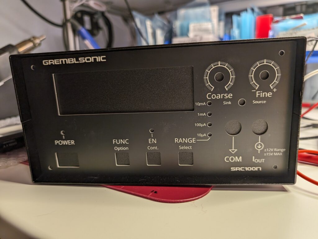
This photo doesn’t actually really do the panel justice. The text and graphics are incredibly sharp (I don’t know if it’s my phone’s camera or the postprocessing it does, or the file format, but the blurriness is entirely a digital artifact — the word “RANGE” is shown perfectly sharp, and the rest of it looks that sharp too in person). There are some slightly smudges on the solder mask (which has kind of a “satin” finish) which come out as much higher contrast in this image than it actually appears in person. I’m really happy with the result and would absolutely use this hack on JLCPCB’s service again in the future.
One problem, of course, is that it’s a flat panel, and the panel that came with the Hammond enclosure has the sides bent back so that screws can attach it to the side of the case. I designed this flange in Fusion 360 to use to attach the front panel to the case sides:
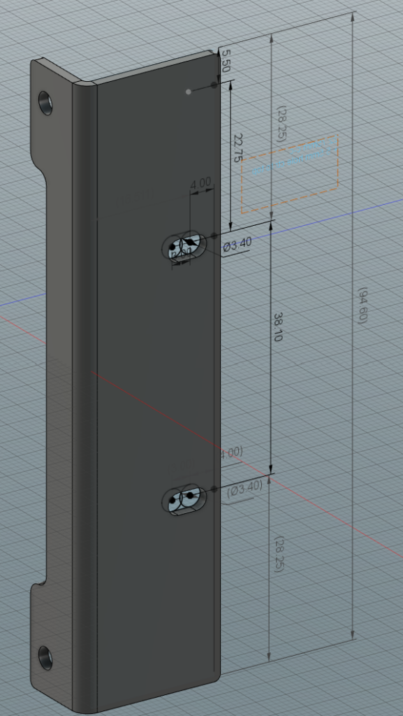
The “thin” side on the left with the holes near the top and bottom will go behind the front panel. A PCB with the front panel buttons, LEDs, etc. will mount behind all of that, with the same machine screws going through front panel, flange, and PCB, with some standoffs holding the PCB back from the first two parts.
This was my first time designing a sheet metal component, but the process was actually fairly easy to figure out. I had it fabricated by SendCutSend, who also have a lot of useful information on their site for configuring “sheet metal rules” in Fusion 360 and listing the various design rules to keep in mind. I then had these laser cut out of aluminum and bent by SendCutSend.
I designed these with oval slots in the sides so that I would have some wiggle room to adjust the offset of the front panel from the front of the enclosure. After I had it sent out for fab, it occurred to me why the holes in the original front panel of the Hammond enclosure were smaller and designed for self-tapping screws — once I put the lid on, and pass a screw through from the outside, I won’t be able to hold the nuts inside with a wrench. Of course. McMaster to the rescue — I was able to find press-fit nuts I could attach to the inside of the flanges. They went on easily enough with vice grips. I won’t be able to use the full extent of the oval track for adjustment, but it’ll still all work.
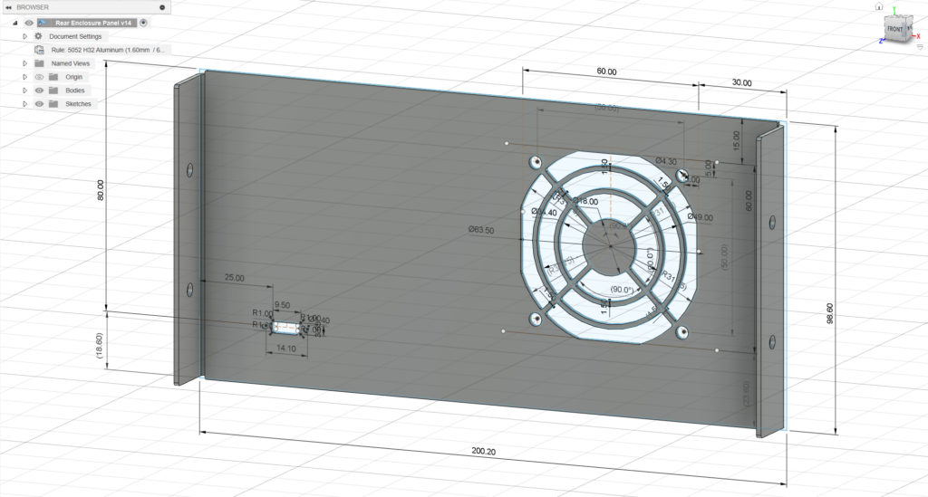
SendCutSend has a $29 minimum order, and the flanges don’t cost remotely close to that. I also had them cut and bend a rear panel for me, with mounting holes and a cutout with grill for a 60mm fan, and another cutout for a USB-C connector, which will provide power:
Incidentally, it is surprisingly difficult to find a USB-C connector with a panel-mount option! They basically all assume you will PCB-mount it and then attach the PCB to the case/enclosure in such a way that the connector lines up closely with a through-hole for the USB plug. GlobTek part JACK-USBC-6SMT-2SL is pretty much the only option I found at a reasonable cost. This still needs a (tiny!) PCB (or a very tight wire soldering job) to break out the pins, but it was easy to design this bit for the job:
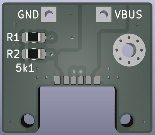
With all of the designs in hand, I ordered the various PCBs and enclosure parts and a raft of components… Read part two for assembly and turn-up.