
I recently started a small electronic art project that involved a 555 timer and EL-wire. Rather than cannibalize the AC inverter from an existing EL-wire driver, I built my own circuit to handle conversion of 6 VDC power from the batteries to the 2 KHz AC power required by EL-wire.
There are plenty of sites to read more about EL-wire and how it works (it’s neat! and colorful!) so I’m not going to reiterate it all here. I wrote this post because I based my design on one from another blog post that lays out an inverter circuit for driving EL-wire, using a 555 timer as the oscillator. The circuit in that post does work (the EL-wire will light up!) but it’s a poor quality signal that (a) doesn’t deliver the full power EL-wire is capable of converting to light and (b) involves high-voltage transients that I believe may be damaging to your components. This post offers an improved circuit that addresses both of these issues.
My goal for this circuit was to take advantage of as much brightness as possible in the EL-wire, even if it means shorter battery life. Other designs may be more efficient or offer longer battery life, but here’s another point on the design spectrum.
EL-wire is brighter with (a) higher voltage and (b) higher frequency. While I haven’t run an EL-wire strand to failure for testing, the datasheet from Sparkfun says that it can operate on an AC signal with an RMS voltage between 20—220VAC, and a frequency of 50 Hz—5 KHz. The sweet spot for efficiency is around 110 VAC and 2 KHz. Although EL-wire is not LED-based, like LEDs, it does consume greater current at higher operating voltages. (EL-wire is capacitive, so higher frequencies make it act more like a “short circuit” as well.) In testing, I found that at 50 VAC power the glow was barely visible in the dark; 75 VAC and up is much better. At 175 VAC, and 2.4 KHz, it really glows, even with the lights on!
Transformer selection
In order to operate at this power point, you need a transformer that is capable of handling that much power. Most audio transformers that have a useful datasheet claim to operate up to 1/4 W. (For some reason, on transformer datasheets, this is always written as “1/4 VA” but, same thing.) I have to assume that smaller transformers like the cheap EE-14 audio transformers you can buy on Amazon (from anonymous/knock-off overseas vendors) are not better at gracefully handling higher switching power than vetted components from Digikey or Mouser. An advantage of those small transformers, of course, is that they are small. Since size was not critical for me, I purchased a slightly larger transformer, model FS10-110-C2. This can handle 1.1 W, and is about a one-inch cube. It is also specified that if you put 5V in one side, you get 115V out the other, which is right around the operating range I’m looking for. While this is meant to run in the other direction (plug it into the mains and get out a 5V signal for use in a smaller device), it works both ways. Also, since it’s tuned for mains voltage, it is most efficient at 50–60 Hz, but it handles 2.4 KHz frequency with no problem; the device did not get at all warm to the touch.
Circuit schematic
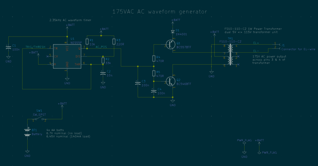
I started by building the circuit shown at theorycircuit.com. It’s very similar to the one on this diagram; the main difference is that their circuit only includes the transistor shown as Q2 above, not Q1. This did cause the EL-wire to glow. I noticed, however, that my benchtop DC power supply was delivering approximately 60 mA at 6V — about 360 mW. EL wire can pull 1.03 W/m at full brightness when operating around 2 KHz, so this was not delivering the brightest glow possible. When I took a look with the oscilloscope, I found more troubling issues as well.
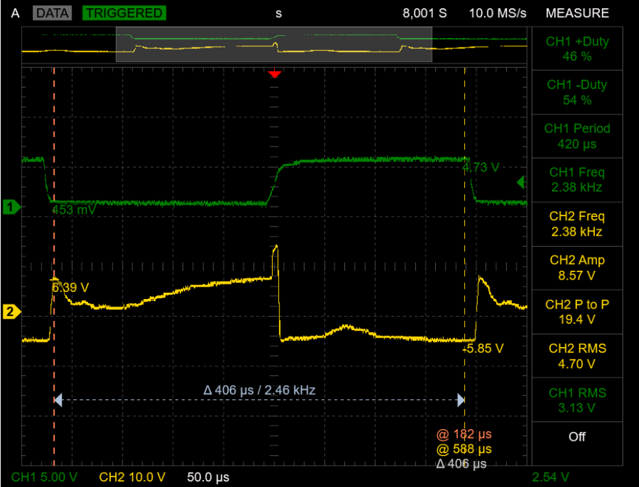
Spiky “AC” power

This screenshot from my digital oscilloscope (DSO) shows two signals. Channel 1 (in green) is the output from the 555 timer U1 (the signal labeled AC_POS in my schematic). When AC_POS is high, the AC power should be on the high side of its cycle. It causes Q2 to close the switch, allowing power from V_batt (6V) to flow through the transformer and down to GND. When AC_POS is low, the switch opens, and power cannot flow in that direction.
The second channel (in yellow) is measuring the voltage across the transistor Q2, over the collector and emitter (which is grounded).
There are two issues with this signal:
- It’s clear that power is only flowing through the transformer during half the duty cycle. In the 555 astable circuit, I intentionally chose a very low resistance (220R) for R3. This means virtually all the timing is controlled by the 33 KOhm R2 and capacitor C2, and it’s as close to a 50/50 duty cycle as possible. Here you can see, though, that when the Q1 switch is open, no current flows through the transformer
- When the 555 switches state from high to low (opening the circuit on the transformer), there are huge voltage spikes. This side of the circuit is running on 6V power, so should never be able to generate the voltages shown there. But the inductor in the transformer wants to keep pushing current forward even after Q2 opens, so Q2 creates a huge VCE voltage in response. Even in the “normal” part of the cycle (when
AC_POSis low), the voltage builds to 143V.
I assume the VCE voltage must be bled off as heat, although surprisingly to me, neither the transistor nor the transformer got especially warm. That said, the ‘scope shows voltage spikes over 200V, and the BC546 has an absolute maximum VCE voltage of 80V. This didn’t pop the transistor immediately, although I imagine it would greatly shorten its working life.
Add one PNP
The solution is to make sure the current is flowing through the transformer in both directions. This youtube video reverse-engineers the (more compact) EL-wire driver circuit in a common EL-wire battery/driver pack, which uses an oscillator based on two transistors.
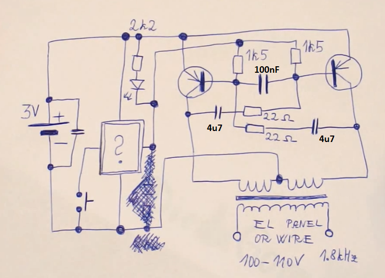
The transformer is center-tapped, and during one half of the cycle, one of the two transistors drives current from the left into the ground/common center, and in the other half of the cycle, the other transistor drives current from the right. This is clever both because it creates a true AC signal with power flowing in both directions as well as because it effectively doubles the input voltage; 3V from left to center and 3V from right to center means it’s running from “+3V” to “-3V” on the input side of the transformer.
In my 555-based design, I added the PNP transistor Q1, which is also driven by the same AC_POS signal as Q2. Q1 is a BC557BTF, which isn’t quite the matched PNP for the BC546 (that would be the ‘556), but this is what I had on hand. (Any NPN and PNP transistors that can transmit ~100mA and handle VCE up to about 40V should be fine, such as 2N2904/2N2906.) Because the output of the 555 timer was not quite reaching VBATT, I couldn’t plug the emitter directly into the VBATT rail. I used a common 1N4001 diode to bridge the gap, which also knocked the emitter voltage down by about 0.7V; now when AC_POS (and thus VB for Q1) is high, it’s definitely above VE, so the transistor is firmly in the cut-off region.
My transformer did not have a center tap, but it does have two separate 5V “output” transformers integrated on the same core. The datasheet says you can use them in parallel (for more current at 5V) or in series to get a 10V output. Since transformers can be run “forward” or “in reverse”, that means I could use them in series to generate a larger AC voltage than 115V as well.
So to refer back to my dark blue schematic earlier in this document:
- Note that the 5V-side transformers are on the left side of the unit, and pay attention to the wiring orientation. One sends power from pin 7 through the inductor and out to pin 8; the other sends power from pin 6 through the inductor and out to pin 5.
- When
AC_POSis high,Q2is in saturation and acts as a short circuit. Power flows from VBATT, through the transformer, throughQ2, and to ground.Q1is in cut-off and acts like an open circuit. - When
AC_POSis low, the reverse is true:Q2is open-circuit andQ1is a short circuit, sending power from VBATT (minus the 1N4001 diode drop) through the transformer in the other direction, pulling the high-voltage AC side along with it, and also smoothly unwinding the residual magnetic field from the first inductor (rather than having it just dump into a huge VCE spike). Since the transformer wiring is reversed in this direction, the battery is sending current through the transformer as if it’s flowing from -VBATT to GND.
As a result, the RMS voltage across the EL-wire side significantly increased, and the signals on the 555/transistor-side are much more well-behaved:
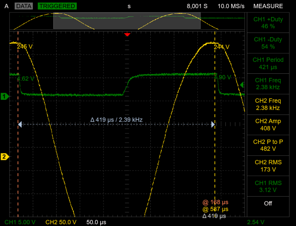
Because of the switching action of the two inductors running in opposite directions, this also rectifies the square wave input into a lovely AC sine wave on the EL-wire side.
And this is now very powerful! The oscilloscope zooms out only to 50 V/div, so the entire output signal doesn’t fit vertically on the screen all at once! My power supply showed it was pulling ~140 mA at 6V, or about 850 mW. This still isn’t quite the 1.03 W that the EL-wire is theoretically capable of drawing, but it is significantly brighter than before; you can see it clearly illuminated in the photo below even with the room lights on. In any case, I am comfortable leaving it as-is without further refinement.
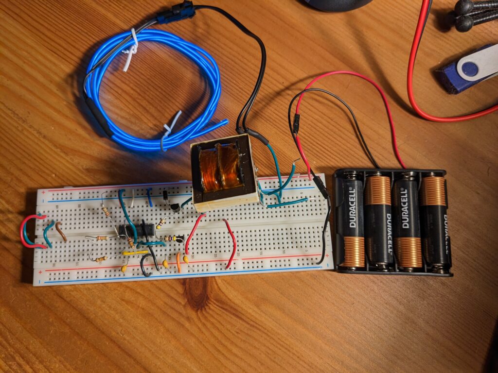
Here’s a photo of the circuit working on a breadboard. A few notes:
- This is actually built on half of an NE556IP dual timer, not a 555. A 556 is functionally equivalent to two 555’s on the same die, although the pin-out is different. I am using timer 1, which is all on the bottom row. The CMOS inputs of timer 2 (top row of pins) are pulled high or low as appropriate to keep them from floating.
- The transformer’s pins do individually fit in a breadboard, but they are not on 0.1″ spacing; I soldered leads to all 8 pins, so it’s kind of “floating” over the breadboard. The empty output pins in the lower right have those two wires just floating in the air and not plugged into anything.
- Q1 (the PNP) is on the top half of the breadboard (next to its diode); Q2 is on the bottom.
- The transformer handled the 2.4 KHz frequency just fine (no extra heat to the touch), but it is a noisy transformer. I don’t think it matters for this application too much, but capacitors C3 and C4 were added to filter out the worst of it so I could see things more clearly on the oscilloscope. Experimentally, 100nF for each works well; 1uF or higher is overdamped and degrades the signal from the timer. I think the “lag” in the rising edge of
AC_POSintroduced by C3 also helps avoid the situation where the PNP and NPN transistors are fighting each other by both being in saturation simultaneously. - I did not have a 33 KOhm resistor on hand, so I made do with a 22K and 10K in series, which jumps out to the left from
Q1pin 1 (lower left) then back to the right to plug into pin 2. - All capacitors are ceramic, 50V-rated. (25V would probably also be fine.) They’re all 100nF except the timing capacitor C2, which is 10nF. (With a different choice for R2, you could probably use a 100nF here as well.)
- Ignore the jumpers on the left edge, those are just extras.
- Because it’s AC, you can plug the EL wire into the transformer in either orientation, it makes no difference. The traces labeled
EL+andEL-are just my convention but you could flip them. - If you build this, watch out for the high voltage! The EL-wire side of the transformer isn’t pulling a ton of current, but it has a very large voltage swing. I accidentally made contact with the transformer while trying to use my multimeter and involuntarily yelled enough to be heard from two rooms away. That incident fortunately left no permanent damage to me or the circuit assembly, but accidents with high voltage can be fatal. Be careful with your fingers when adjusting any probes while the circuit is on.