
I recently designed a custom case to fit a Raspberry Pi 4 and a 7″ LCD screen.
I wanted a small tablet-like computer I could set up to look at while seated at a table, or standing at a counter in the kitchen. I often cook recipies from the internet, and find myself either trying to use my phone while cooking (hard when I need my hands for cooking, or they’re dirty), or walking back and forth to the next room to look at a computer monitor (annoying).
I had recently gotten a Raspberry Pi 4 to tool around with, and also picked up a 7″ LCD touchscreen. A rectilinear “box” shape like I used for the sailboat racing computer wouldn’t work for this, because I would need to either have it facing totally vertical or totally horizontal, and neither of those are good viewing angles. (The sailboat racing computer is mounted on an adjustable arm from RAM-Mount.) I wanted a case with either a kickstand or an angled face to lean it back.
My CAD skills are very amateur, but this was a fun project to improve them.
Parametric CAD modeling
A friend of mine with an actual mechanical engineering degree gave me a quick tutorial in CAD modeling earlier this year. As a software engineer, the way this works actually makes a great deal of sense to me: you essentially use a GUI to write a computer program of declarative functions that, when executed, renders the model you want.
These functions consist of 2-D sketches, extrusions of those sketches into 3-D bodies, and actions on those bodies like “chamfer edge”. There are also functions to define invisible “construction” objects like lines or planes that can be referenced downstream (e.g., to mirror an object over a “construction line” defined along the midpoint of a face) but don’t directly contribute to the visible body.
2-D sketches can contain circles, lines, rectangles, etc. with defined dimensions or offsets from one another, and can also include constraints like “must be parallel (or perpendicular) to this other line”, “is as long as this other line,” or “is centered on this other point.” The “other line/point” here could be in this sketch, or any previously defined sketch. These sketches are extruded into 3-D shapes which can then be further refined (being hollowed out; having holes cut in them; using fillets or chamfers to mill the edges; and so on).

This builds up a timeline of actions. While it’s shown linearly, it is actually a tree in the CS sense where elements can be reordered, but no earlier than any element which it uses as a dependency. In the image above, you can see several actions being taken: creating a sketch, extruding a 3D body from it, creating another sketch and extruding another body, chamfering edges, and onward. The controls shown on the left side of that timeline allow you to “rewind” and “play back” the timeline to see how the final model is built up step by step.
A crucial insight to the mental model is that if you go back and edit an existing sketch, that doesn’t add a new activity at the end of the timeline—the timeline is not the “undo stack” like in a text editor or Word document. Instead, the timeline is the sequence of “function calls” in your rendering program, and you’re revising one of those functions. The extrude, fillet, etc. operations that follow it in the timeline will then re-execute in terms of the revised sketch. So if you first sketch a rectangle and define it as 3″ x 2″, and extrude a 1″ tall box, you’ll have a 3″ x 2″ x 1″ cuboid. If you then go back and revise the sketched rectangle to be 3″ x 3″, the existing extrusion operation can interpret the revised sketch and automatically adjusts to create a 3″ x 3″ x 1″ box. And any other subsequent sketches with constraints that reference the dimensions of the first sketch will also adjust automatically as well.
This is called parametric modeling, as the steps in your model timeline are, well, parameterized in terms of one another, rather than being a “sculpt the model out of clay” activity where every action is an isolated modification of the object as a monolithic whole (like revisions to a Word document are). Virtually all modern CAD systems work in this parametric fashion, which both allows models to be tweaked if the design requirements change, as well as offers numerical precision that enables advanced mechanical simulations and analysis for models with moving parts or high-stress loads.
While the mental model made a fair bit of sense, actually building something in these terms is still pretty challenging. CAD systems are serious power tools with a steep learning curve. And trying to select the right object to reference or modify can devolve into an exercise in willing the computer to interpret your mouse pointer the way you are. After a quick rant on Facebook, that same friend reassured me that most CAD modeling time is actually spent tediously attempting to get the CAD software to highlight the point, face, or line that you think you’re hovering your mouse over, so I must be on the right track.
Another challenge is that the “debugging” interface is also quite poor. The system won’t let you over-define your model. If line A is constrained as parallel to B, and B is constrained as parallel to C, you will get an error if you then explicitly attempt to constrain A as parallel to C. (Or if you try to constrain A and C as perpendicular.) Unfortunately, the error message essentially boils down to "Error: model is overly constrained", rather than telling you why it’s over-constrained. And while constraints are shown as small icons near the relevant points or lines, actually interpreting which other objects are linked on the other side of those constraints is often impossible. Especially since you can turn on and off visibility of each sketch or body independently, you can often find yourself hunting for a constraint against a line that’s impossible to see.
The case design
Nevertheless, after working on this for a couple of days, I was able to successfully build a model for the case that I was satisfied with:
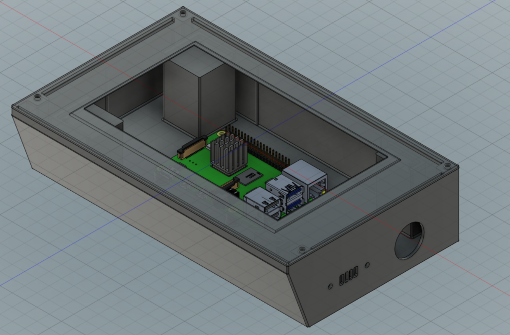
The case is almost a rectangular cuboid, except the front face angles back by 20°, allowing the screen to be tilted back when stood up, for a better viewing angle from above.
The lid on the top attaches to the case body through four screw holes that match with threaded holes in the body. The lid mounts flush to the corners of the top of case, and has registration flanges which fit directly inside the case body, to help with alignment as well as a better (though not waterproof) seal. To enable a good fit on the front face, the top of the front panel starts out oriented vertically for a few mm before beginning to angle back.
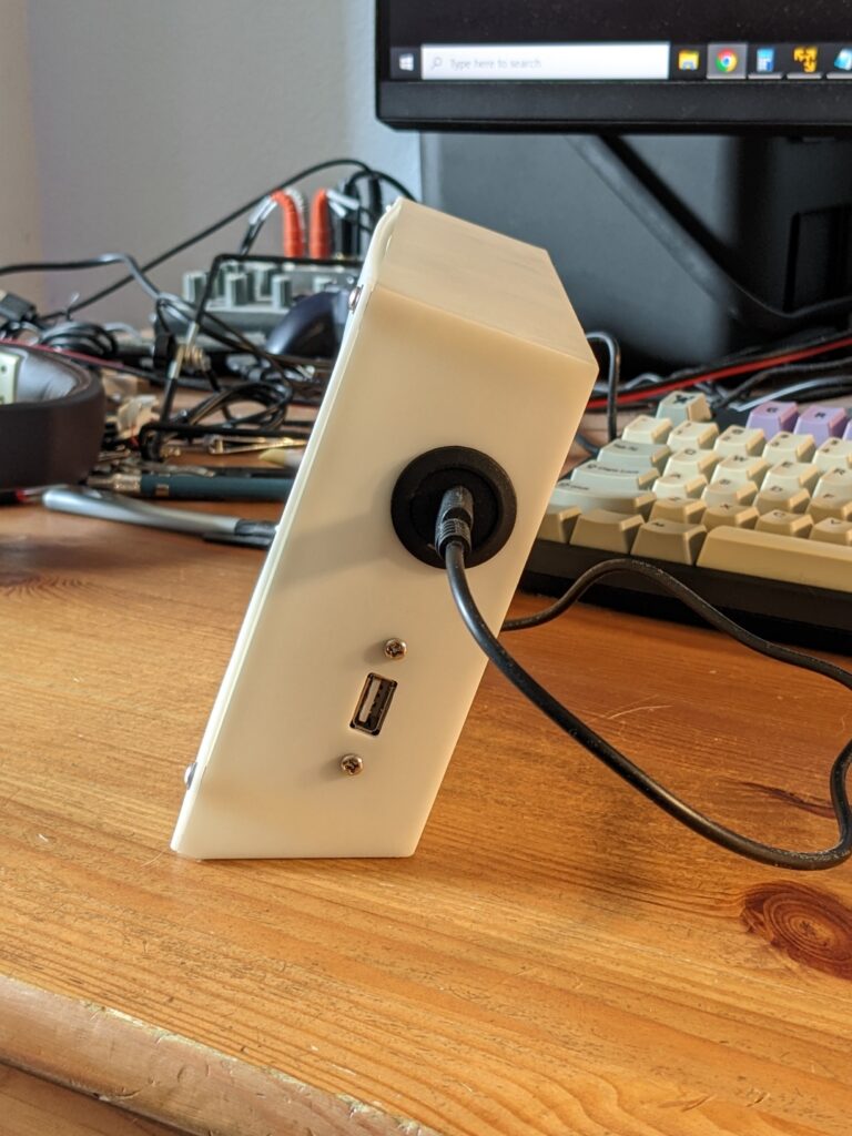
On the right side of the case body, a circular cut-out will hold a USB-C extension port that provides power to the Raspberry Pi inside, and a rectangular cutout with screw holes on either side provides room for a panel-mount USB-A port for peripherals like a keyboard. The rectangular cut-out contains some vertical support pillars for printability purposes, which I’ll cut away before installing the panel mount port.
In the sailboat computer project, I was working with an existing case, and had basically no option for LCD mounting except to attach it directly to the lid, with screws that penetrated the lid around a large cut-out for the screen. Doing this with the required precision wound up being quite the odyssey. For this case, since I was defining everything parametrically and then having the whole object printed at once, creating holes for screws that match up at the precise required distance to the screen cut-out would be much easier. I also would prefer, though, that the screws don’t show on the lid. My friend suggested mounting from below on “pillars” that hold the LCD up against the underside of the lid:
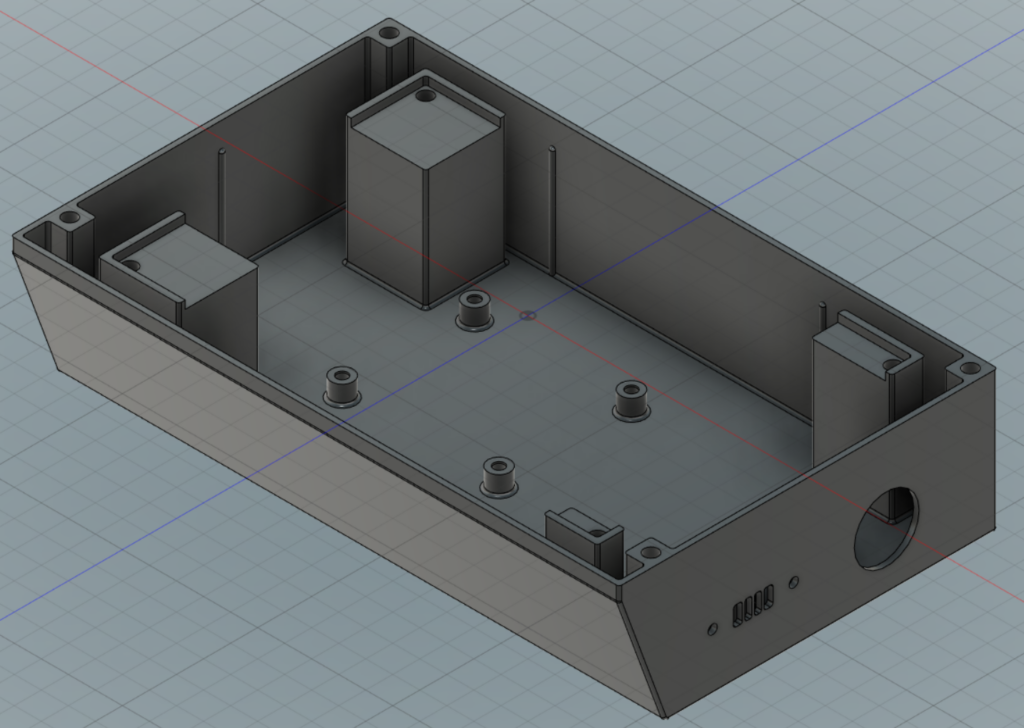
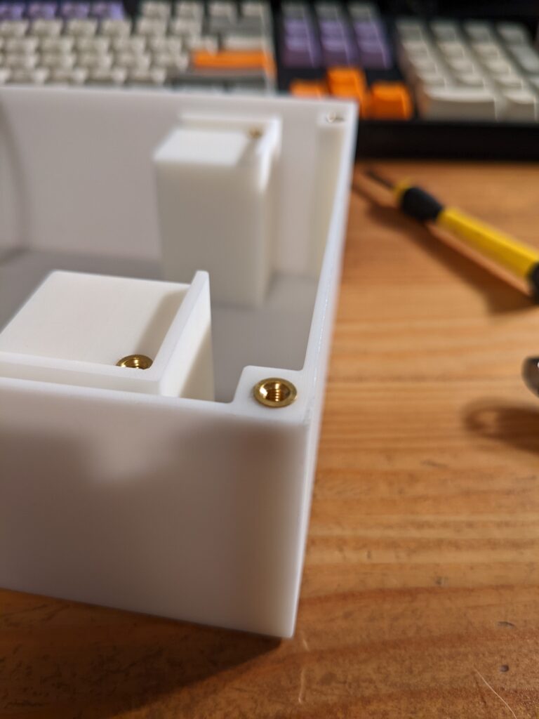
Here you can see the body for the case with the lid and internal components removed. The four pillars fit around the edges of the LCD, and contain cylindrical channels for mounting screws, just like the internal flanges that contain mounting screw channels that align to screw-holes in the lid, and the mounting bosses on the floor for the Pi. The pillars on the left are larger to provide firm support for the LCD; the ones on the right had to be made smaller to accommodate the HDMI and micro-USB ports that extend rightward from the underside of the LCD device.
The holes are not actually directly threaded in the 3-D model. You can 3-D print threaded holes, but it’s recommended to do so only for size M6 screws and up. These holes are slightly oversize, and will contain metal heat-set threaded inserts sized for M3 screws. (The link there is to a hobby maker site that lets you buy a few inserts for $0.20 each. You can find similar inserts in all possible sizes at McMaster, but you need to buy them in packs of 100.) The inserts are easy to install: place one over the hole, and heat it with a soldering iron. As the plastic heats up around the insert, you push it down into the hole with the soldering iron and the plastic remolds around exterior grooves in the insert that hold it in place against the action of inserting your screw.
I built this model in Autodesk’s Fusion 360, which is a very powerful and complete software tool, and is also free for amateur use (with some limits on how many “active” files you have, and also doesn’t give you access to more advanced tools like stress analysis). Another free option (for not-for-profit use) is OnShape, although there your models are all made public.
Fabrication and revisions
I don’t own a 3D printer, but got this fabricated on demand at JLCPCB. (Yes, the same place I used for PCB fabrication.) I checked for quotes with some domestic manufacturers first, but their prices for this object were extremely high. (Like, far more than the cost of just buying a 3D printer.)
The price depends on how much feedstock material would be used to fabricate your item, and also what material you use. Most home 3D printing is done in PLA using a technology called FDM (fused deposition modeling), also known as FFF (fused filament fabrication). In fused deposition modeling, plastic is heated and extruded through a nozzle (like a hot glue gun) that builds up your object layer by layer. JLCPCB would use FDM and PLA if you want, or many other materials as well. They support several different 3D printing technologies, each of which supports different sets of materials in turn. The most inexpensive they offer is a resin-based 3D printing technology called SLA. SLA, or stereolithography, is a process where your object hangs under a flat surface and is built upside-down: the bottom of the object is dipped in liquid resin and a UV flash in the precise image of the next layer exposes and cures some of the resin to adhere that next layer to the workpiece. Having this case built by JLCPCB via SLA in 9000R Resin would cost about $28 + shipping.
I sent them the exported STL files for my model, and then heard back from them that I’d need to make some adjustments: my case lid overhangs the top of the LCD (over the non-active-screen area) and I had defined that overhang as a very thin layer of 0.4mm; I wanted it to press close against the screen and have essentially no bezel, so that the LCD and surrounding case would be a perfect “flat screen.” The 0.4mm layer area was not likely printable, I was told, as it would probably warp during printing of the rest of the object. I didn’t like the idea of having the LCD be totally unsecured from above — i.e., deleting the overhangs — so I thickened it up to 0.8mm (their recommended minimum), added a slightly rounded edge to make a bezel, and resubmitted the file.
Assembly
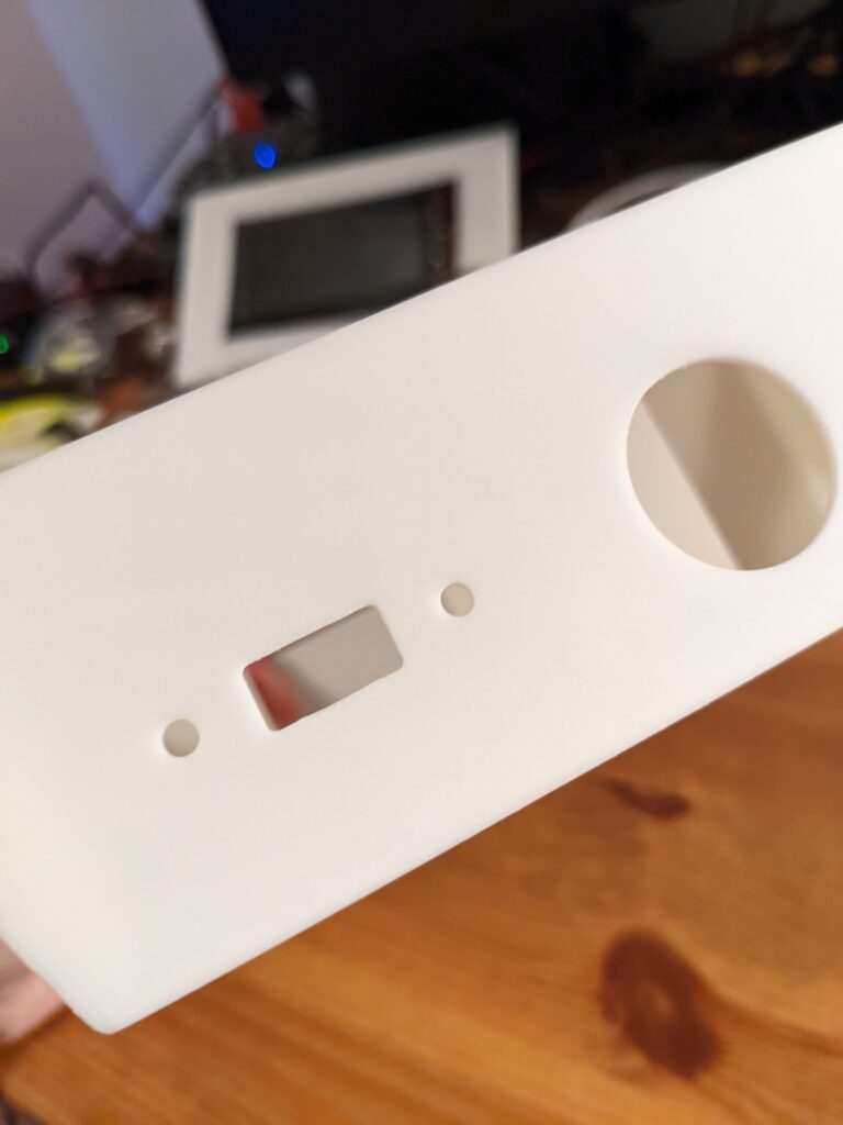
Two weeks later, the case arrived arrived from JLC, neatly packaged in bubble wrap:
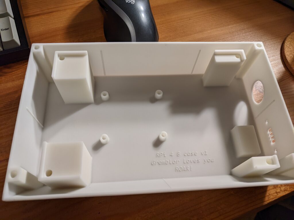
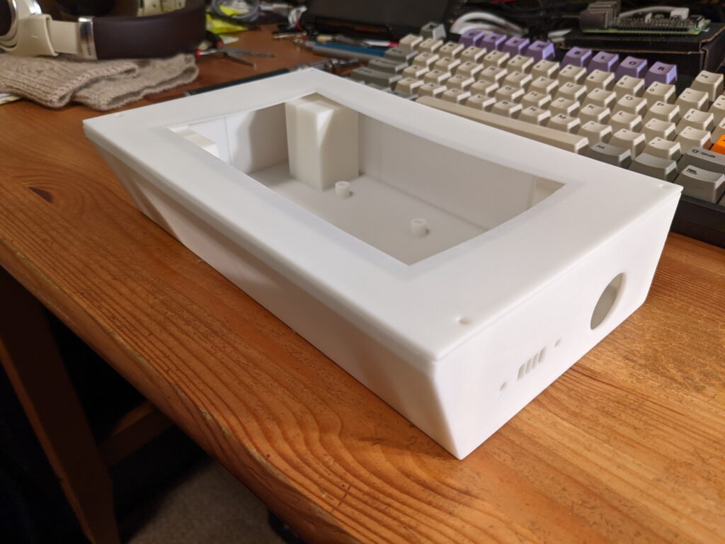
Overall, the print quality is amazing. It really did arrive fabricated almost exactly as-designed. The lid fit snugly against the walls of the case body, with the internal flanges lining up nicely along the side walls. One issue that’s obvious from the photo is that while the screen bezel did print correctly at its increased 0.8mm thickness, the lid as a whole does a noticeable warp to it. In fairness, I was warned about this possibility—large, thin, flat shapes can be hard to print in SLA. An immediate regret was that I only designed in holes for mounting screws at the four corners; if I had added two more screws at the midpoint along the top and bottom edges, it would have held down the bowing much better.
Panel mount accessories
Before the components can be assembled, I would need to remove the supports from the panel mount hole on the right side. I had assumed that the case body would be printed flat, bottom-to-top. Wary of the 1.5cm “bridge” that would be needed at the top of the USB-A panel mount hole, I added my own support columns within the hole. In fact, rectilinear objects printed in SLA are often rotated 45 degrees (i.e., a cube would be “sitting” balanced on a corner point) with support columns holding the object to the bed. As such, the USB-A wasn’t actually going to be a real bridge, and those supports were unnecessary. In any case, it was easy to remove them with the sanding tip on my Dremel running at low speed. Some manual finishing of that port cutout with 220-grit sandpaper and the case body was ready.
Threaded inserts for screws
Several components of this system would be joined with screws: the Raspberry Pi would be screwed into the floor of the case, and the LCD secured to its mounting pillars by more screws. Finally, the lid would also be attached to the case body with screws. I used heat-set threaded inserts to provide the threaded channels for the screws. The LCD and lid were size M3 and the Raspberry Pi itself requires M2.5. The holes I prepared were each slightly larger than the associated screw width and slightly narrower than the outer diameter of the “barrel” of the threaded channel.
I set each insert resting on top of its associated hole, turned my soldering iron on to its lowest temperature (270° C), and gently pushed each insert down with the tip of the soldering iron until the top of the insert was flush with the top of its mounting boss. Over about 30 seconds, each insert lowered itself into the hole, with its grooved exterior sinking into the resin that surrounded it. This was clearly designed for a thermoplastic like PLA, which would have reflowed much more easily. The resin didn’t melt (and some of it seemed to be expelled as tiny bits of dry dust) but the channel did deform enough to admit the insert and secure it in place.
Installing the smaller M2.5 inserts didn’t go quite as smoothly. The ratio of hole diameter to the OD of the insert was different than for the M3 inserts. The longer and wider M3 inserts had an angled lower edge that sat comfortably inside the hole and helped push it open as the insert was lowered into place. By contrast, I used the “short” profile M2.5 inserts (since the screws were only 6mm long) which were a hair wider than the hole and were gently balanced over them to start. As a result, the mounting bosses for the Raspberry Pi each split with some thin cracks as I pushed the threaded insert into place:
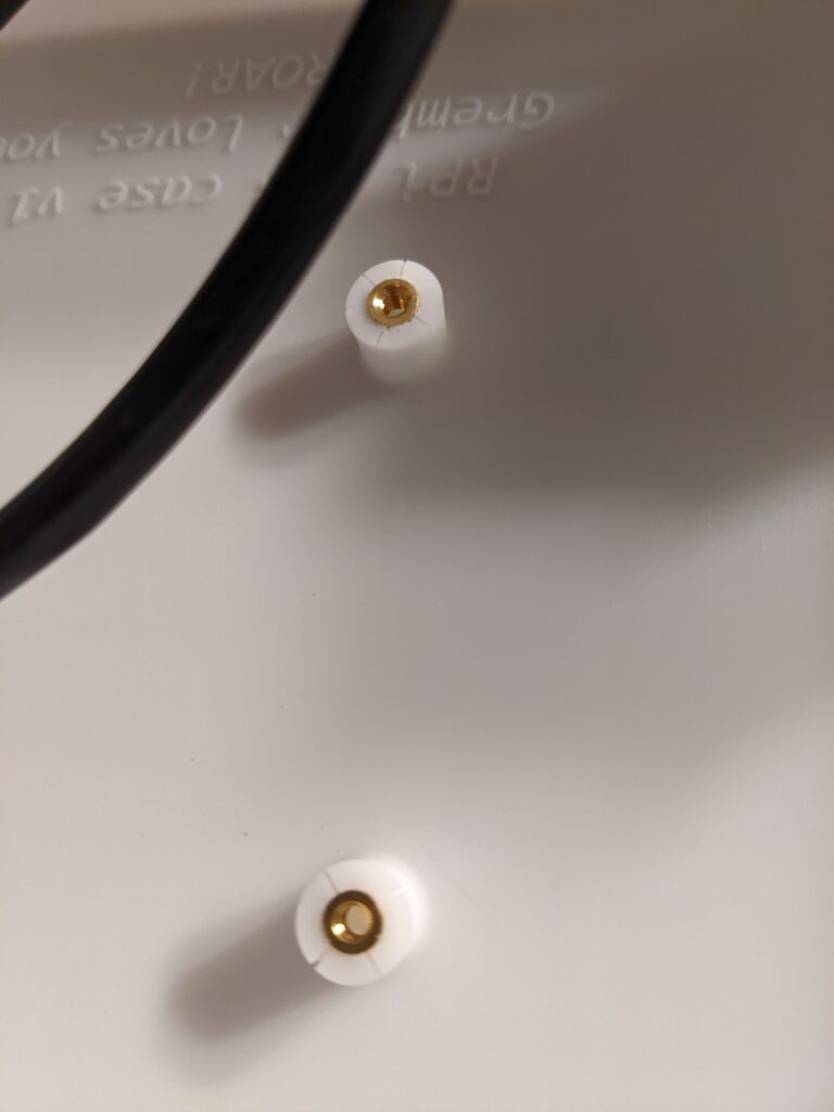
As a note for next time, the manufacturer’s guidance on hole diameter for these inserts isn’t correct (at least for SLA), and I would make the starter holes wider. Nonetheless, once cooled, the inserts were securely in place and I was able to attach the Pi to the case without difficulty.
Wiring it up
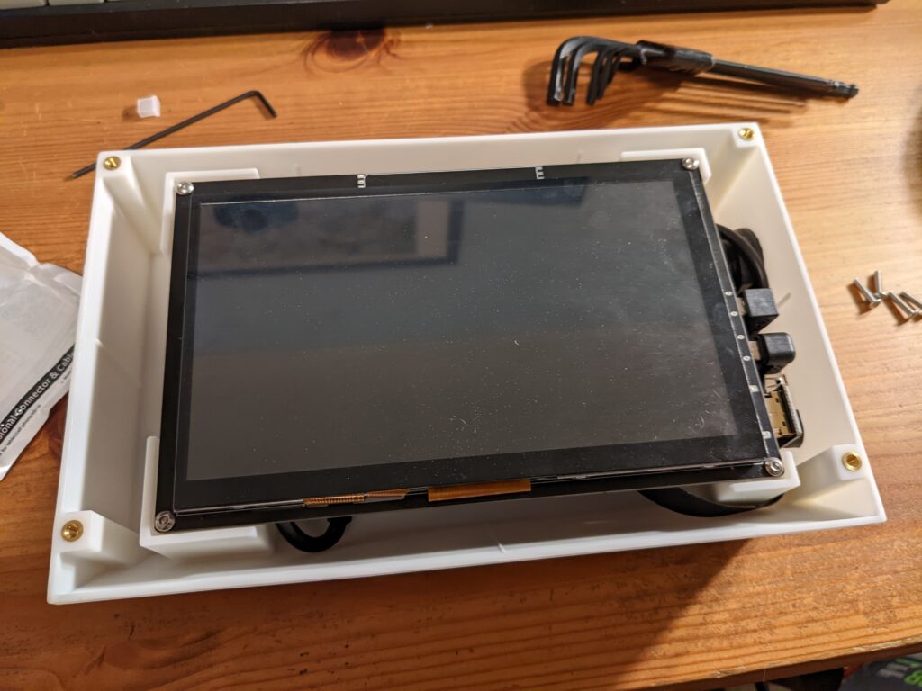
It was then very simple to screw in the Raspberry Pi, add the panel mount sockets and add the internal cable assemblies that would attach the Pi to the LCD.
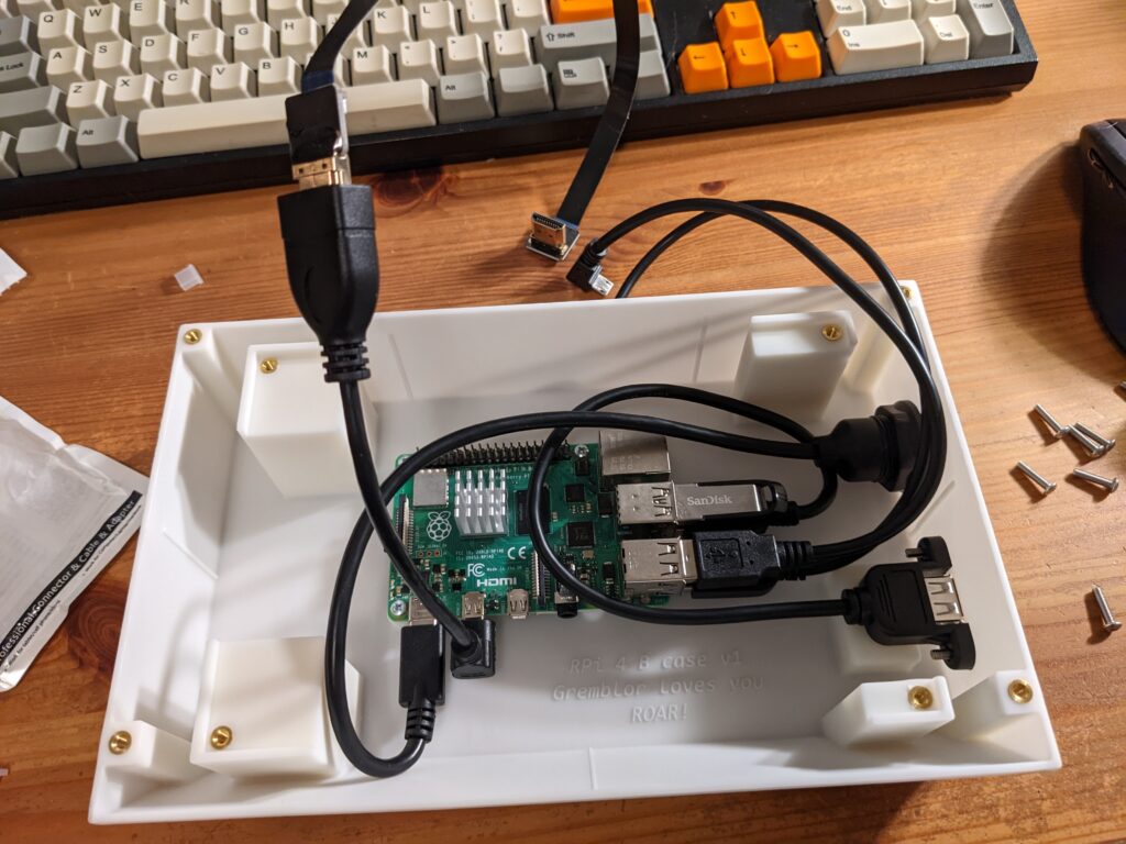
The Sandisk USB key shown there is a complement to the microSD card used to boot the Raspberry Pi; the root volume lives on the microSD card, and the 16GB USB key—also formatted in ext4—provides extra space for user files. The USB key is attached to a USB 3.0 port on the Pi, along with the external USB interface, and the two USB cables required for the touchscreen are mounted to the Pi’s USB 2.0 ports.
I also mounted a small heatsink on the top of the BCM2711 SoC on the Raspberry Pi. The SoC will throttle the CPU if it gets too hot during heavy CPU loading. According to Adafruit’s testing, this $2 investment adds 20% more performance during a stress test—not bad!
Then I attached the other ends of the cables to the LCD, set it on top of its mounting pillars, and screwed it in place. I had to gently persuade the USB cables to bend enough to not push the LCD out of the way, but it all fit eventually.
The result
Finally, it was a simple matter of screwing on the lid, and plugging in the external USB-C power cable.
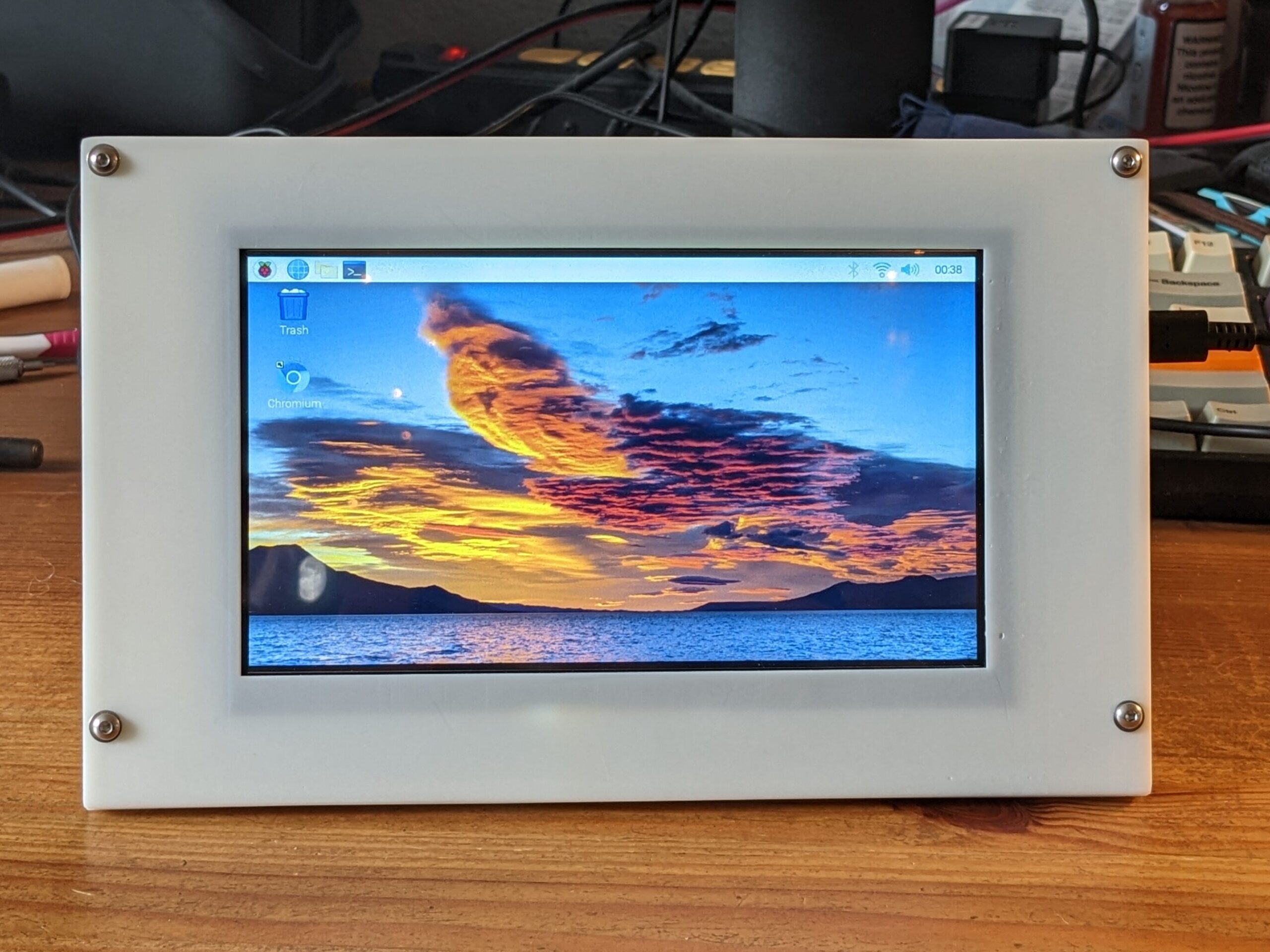
The screen looks pretty good, and the bezel is well-situated to the LCD; none of the active screen viewing area is hidden, and the bezel covers most of the inactive glass. The touch sensor surface is actually slightly smaller than the active area of the LCD (there are a few visible but non-touch-sensitive pixels around each edge), so the bezel doesn’t get in the way of using your finger as a cursor, either.
The case by itself won’t stand up at the 20 degree lean enforced by the angled front face of the case. But with most of the weight being in the LCD, which is pressed against the forward edge of the device, the center of gravity is very solidly in the middle, and it feels pretty secure while stood up. It is possible to knock it over, of course, but it actually has a decent amount of righting moment. Pressing against the touchscreen, for example, really doesn’t move it at all.
What about a keyboard?
You can plug a mouse or keyboard into the USB-A port on the side of the case, which is forwarded to a USB port on the Pi itself. While the touch sensor means you don’t need a separate mouse, I also didn’t want to plug in a keyboard every time I used it. After testing a couple of options, I settled on the onboard virtual keyboard:
sudo apt-get install onboardYou can load the keyboard by clicking the menu option: (Raspberry) > Universal Access > Onboard. Once loaded, it can be configured to appear whenever your cursor is in a text box, and otherwise hide itself. This does require some Ubuntu accessibility capabilities to be enabled, which were not installed by default. To install those required running:
sudo apt-get install at-spi2-coreIf you turn on the “auto-show when editing text” option in Onboard, but don’t also install that dependency, the keyboard will fail to load the next time you start up the Pi. I feel like this should have been auto-installed with Onboard through apt, but it was an easy-enough fix.
Errata
If I were to reprint this case, there are a few things I’d revise first:
- Add two more screw holes at the midpoint of the long axis above and below the screen, so the lid screws into the case body at six points instead of four, to prevent the lid from bowing once installed.
- Add stiffening ribs along both axes on the underside of the lid to help prevent warping. Also make the registration flanges slightly deeper.
- Enlarge the radius of the holes for the M2.5 threaded inserts in the Pi mounting bosses to avoid cracking when installing the inserts.
- If printing in SLA, eliminate the vertical supports in the USB-A panel mount cutout, since the print angle means that doesn’t require printing a horizontal bridge.
Some other future work would also be to add a USB-A port on the left side of the case (which could be run through the LCD, which is also a USB hub), expose the 40-pin GPIO port to the exterior of the case, and perhaps also wire a power switch into the USB-C, using some kind of inline adapter.
Wrapping up
This was a fun build! I definitely feel more confident in my CAD skills after working through this. And without needing to do a ton of electronic engineering or software development, the process to get to a working result was definitely a lot faster than some of the more ambitious projects I’ve done in the past. This will be a handy little “tablet” tool to have around the house.
And if you’re curious or want to build this yourself, here’s the BOM for all the components I used, along with the 3D model for the case (STEP, STL for the body and lid, or Fusion 360 archive).
Edit 12/9/2022: You can also download a “v2” 3D model that addresses errata #1–3 listed above (STEP, body STL, lid STL, Fusion 360 archive). As a disclaimer, I have not printed this version of the model. Supports remain in hole for USB-A jack, so you can print with FFF if you want. You need to add two more M3 bolts, washers, and threaded inserts to the quantity shown in the BOM.