This is the sixth post in a series about building an embedded electronic device to assist in sailboat racing.
Marine electronics project — table of contents
- Project background
- The platform
- A digression on suppliers…
- The software
- Power and packaging
- Fabrication and assembly
- Mounting and installation (take one)
- Installation (take two) — Success!
Now it’s time to put it all together! Mechanical fabrication is one of my weaker skills and this is where having handy friends really helped pay off. My friend Matt was instrumental in helping me get it all together.
The lid
The first order of business was cutting a hole in the lid to mount the screen. Actually, cutting five holds in the lid. The tolerances here were quite tight: I needed a rectangle cut out exactly the size of the screen, with nice sharp edges. The four mounting bosses needed to be below drilled holes that would line up precisely. And it needed to be offset to the left by just a bit to facilitate those cables — but there’s not too much room to the left either.
Our first thought was to use a laser cutter we had access to, which would use as input a simple vector drawing of where to cut, and had the ability to slice through a lot of materials very cleanly. Unfortunately, we found that polycarbonate reacts… poorly… to this treatment.
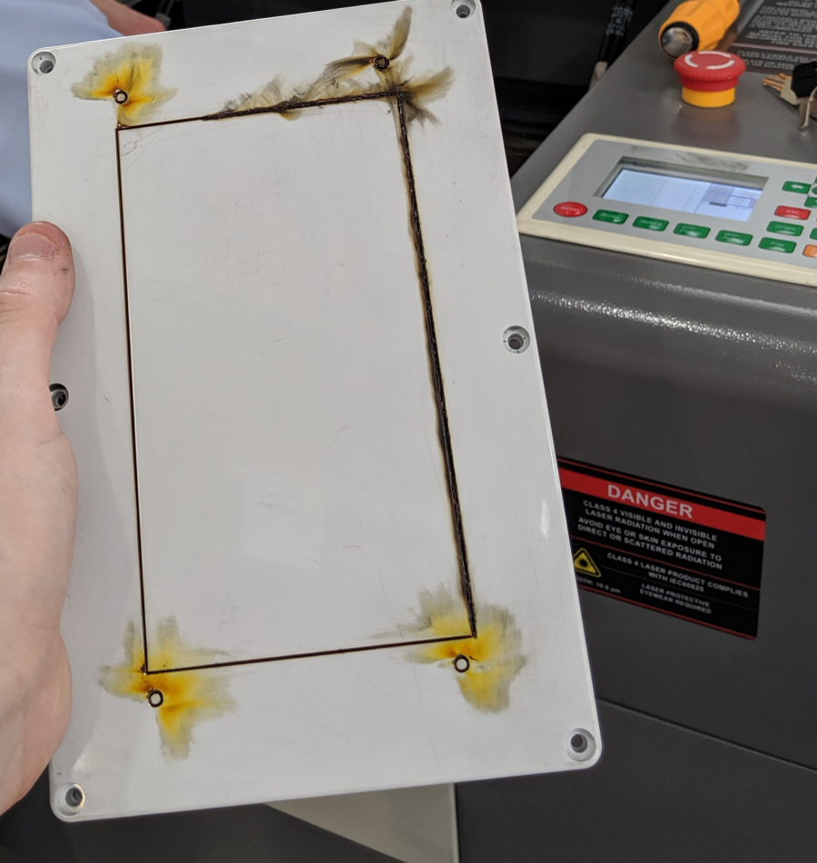
In hindsight, this may have worked if we had used different settings; with lower laser power, higher laser traversal speed, and multiple passes it may not have heated the plastic to the point where it scorched. Nevertheless, we did not repeat this experiment.
In any case, I was off to find someone with access to a CNC mill. (And place a new order with Polycase.) My friend Tom had a small OtherMill (he actually helped work on it at Other Machine Co.), which is a really neat tool — but its bed is too small to fit the case lid.
He connected me to his friend Randall, though, who has access to a much more powerful setup.
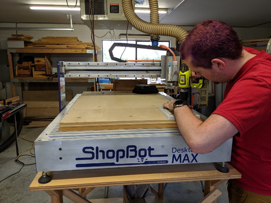
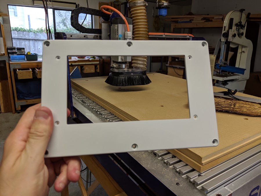
“Measure twice and cut once:” Using this tool took about two hours of setup for a job that took 45 seconds to actually complete. The ShopBot is a powerful mill with an expansive bed; its typical job as installed here is precisely cutting out several pieces from a half sheet of plywood. It would definitely get the job done. The tricky bit is that it has very high relative precision, but its usual jobs did not have especially high requirements around absolute precision: you would put a large piece of plywood on the worktop and it would cut several pieces out of them. But lining everything up so that it would make the cuts within 1/4″ of where they needed to be on the lid without being too far to one side or the other took some careful work. Fortunately, we had the other scorched lid to use for testing first. Once we finally hit “go,” though, the result was fantastic:
Internals
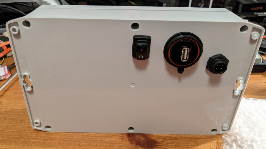
Matt helped use a drill press to make holes neatly in the back of the case for the connectors, as well as set up the mounting plate to neatly fit everything and make space for the connectors to come up from beneath.
Then COVID happened, and I forgot about this for a while.
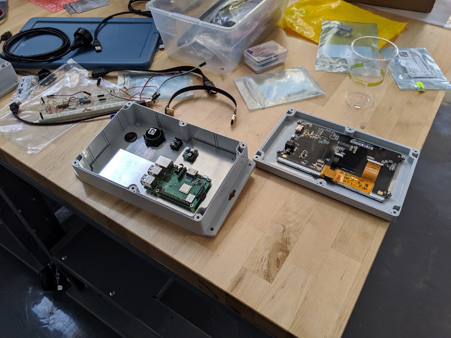
But I eventually picked it up again and there wasn’t much left to do to get it over the line. I soldered together the internal wiring for the switch and some of the internal power cables, and completed the rest with jumper wires and connectors. And here you can see it all coming together!
The various cables and wires take up an impressive amount of the internal volume. It does all fit, though.
I also needed to add a gasket between the screen and the underneath of the lid to both ensure a watertight fit as well as alleviate pressure from above that might crack the edges of the screen. I used an X-acto knife to carefully cut a thin “window frame” out of a 1/32″ silicone mat, and then used silicone adhesive to mate it to the underside of the lid:
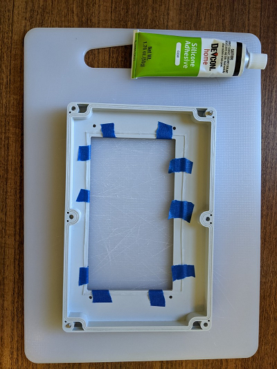
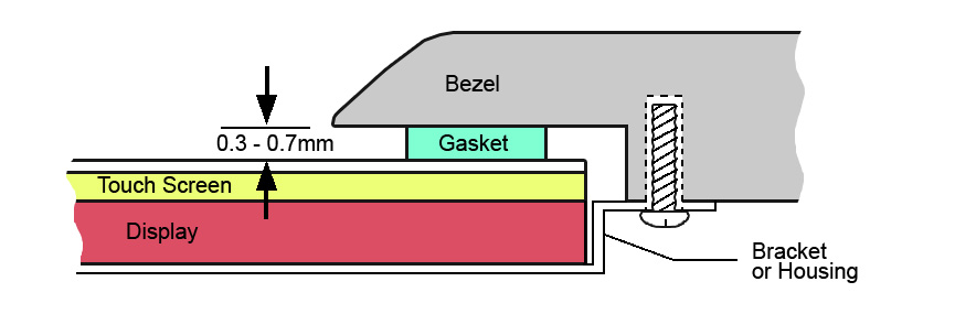
Silicone is great because it’s waterproof. It’s also basically everything-proof; the only kind of glue that sticks to silicone is… more silicone. I had to buy a tube of liquid silicone adhesive for this. I then used a toothpick to apply it to the thin gasket, and carefully lined the gasket up on the lid. The display’s mounting guide gave very precise specifications for how far it needed to be from the edges of the screen, and it couldn’t go too far in from those edges because then it would protrude into view:
Especially given what it took to cut this lid to precision, I really didn’t want to screw this part up. But it came together fine in the end.
Before sealing it up, I also applied a healthy amount of hot glue to the connectors on the inside of the case. This would help with any last watertight issues; I also noticed that attaching and unscrewing cables from the outside was enough torque to rotate the connectors and cause them to come loose from the plastic retaining nuts inside the case without some adhesive.
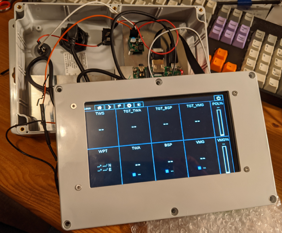
It’s alive!
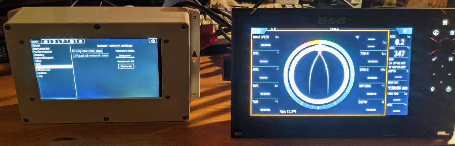
It finally did come together though, and it looks and feels really solid! I’m rather pleased with the end result. For good measure, I connected it to the MFD and while there were no other instruments sending data, I verified that it was receiving N2K packets over the bus as sent by the MFD.
I learned another small lesson based on a minor cosmetic flaw visible in the photo above. The actual LCD does not cover the entire top surface of the display device; you can see a thin “dead” band on the right side of the screen which is just black glass. I later consulted a schematic drawing of the display and realized that the active area is marked on it—it’s slightly off-center! Had I realized this in advance, I would have milled out a slightly tighter window to avoid that stripe — but the end result is still totally acceptable.