
This is the eighth (and final!) post in a series about building an embedded electronic device to assist in sailboat racing.
Marine electronics project — table of contents
- Project background
- The platform
- A digression on suppliers…
- The software
- Power and packaging
- Fabrication and assembly
- Mounting and installation (take one)
- Installation (take two) — Success!
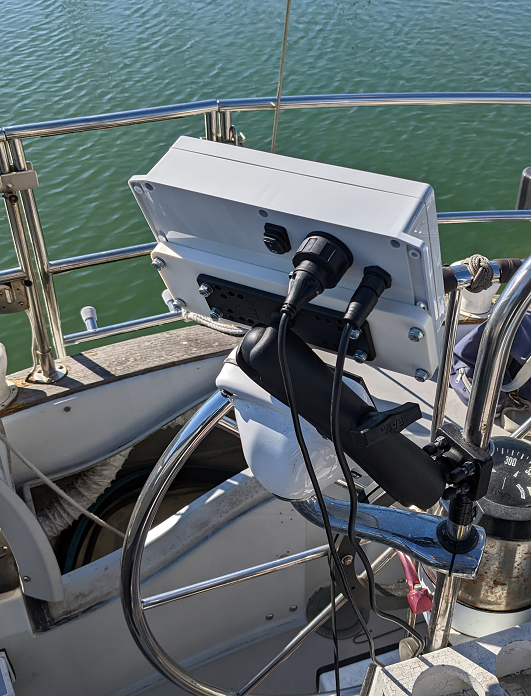
After some more procrastination, it was time to wrap this up. I was, in fact, able to get this successfully wired up and mounted on the boat!
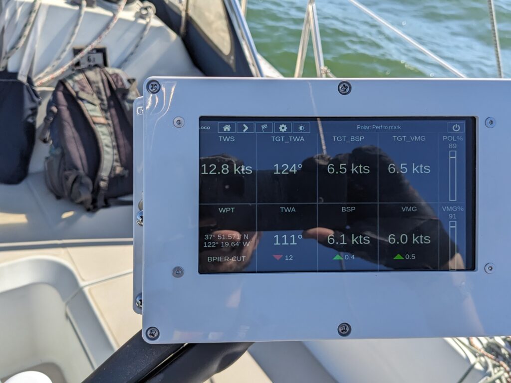
Installation - The finished product, in situ
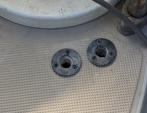
I finally picked this back up this Fall (2022). Installing the cable glands was actually very straightforward, once I got over the psychological hurdle of drilling a hole through a perfectly good watertight cockpit deck. First I chose the sites (after several more awkward trips into the transom locker to confirm I’d be able to pull the cables through from there), and sanded down the anti-skid on the deck’s gel coat where I planned to attach the gaskets. (This was a quick job when done by hand with #80 sandpaper.)
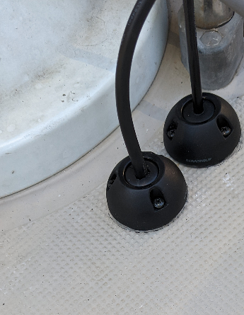
Then you attach a gasket with an adhesive backing, and drill the deck hole through the center (9/16″). I used a regular spade bit which did just fine on both the fiberglass deck and the plywood underneath. You then screw in a mounting base, put a rubber “bung” around the cable, and screw the crown down onto the base. The result is pleasingly watertight-looking.
I was also finally able to locate the right power cable: when looking at the rat’s nest of wires that come up to the cockpit, I found one with some obvious taps off of it for fused connections to the MFD and radar. I was able to use my multimeter to verify that the fuses in question were at +12 when only the “instruments” breaker was on, so it was a simple matter of splicing another wire onto this line with a crimp connection.
And the NMEA2000 connection was of course straightforward, just add another tee to the N2K bus and connect the NGT-1 to it. (NMEA2000 is refreshingly “plug and play” compared to most stuff on board a boat.)
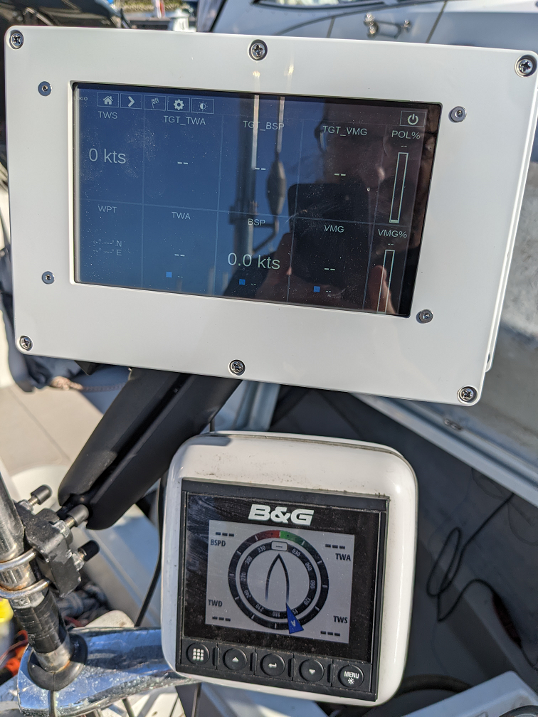
Finally, it was time for the moment of truth… I connected the cables to the device, flipped on the “instruments” breaker, and switched on the power… and it worked! The device booted up smoothly and read the (uninteresting) boatspeed and wind speed data from the network. (Both are 0 since I’m at the dock on a calm day.)
Reflections
All in all, I had a great time making this project and learned a lot.
Cost
I was somewhat surprised in the end how much I spent over the course of this project. Ordering the whole BOM would have been $658 on parts, $47 on sales tax, and $76 on shipping, for a total of $781. In practice, I probably ordered about $50 more in reorders (and another ~$30 worth of shipping) due to ordering some things incorrectly and damaging a couple of parts. Beyond that, some things had to be purchased in greater quantities than actually used (the 1/32″ silicone sheet was big enough to cut out 3 window gaskets, so I only used $9 worth of the $27 I spent on it); the “official” BOM cost for one unit is closer to $720.
On top of that, I spent another $260 on tools, a DC power supply, and extra components for bench testing. So all told, almost $1100! Which is a lot when you add it up. It’s still cheaper than shelling out for a professional-grade racing device, and especially since the cost was meted out over a couple of years, it never hit my wallet particularly hard at any one point. (And, hey, I had fun and spending on hobbies is valid. I have also reused these tools for later electronic hacking projects.) But I was still surprised that the base BOM cost for this project wound up to be such a substantial fraction of the commercial option’s cost. It’s widely acknowledged that those have a significant markup (everything in boating is; and the market is not huge). Yet you might expect the DIY route to be even better savings. Of course, I didn’t do any D4M, nor am I getting the price breaks of bulk purchasing. I imagine I could push the cost a fair bit lower if I were really setting up to do a proper manufacturing run. Of course, at that point the fact that all the labor to this point was free starts to come into play, too.
If you’re interested, I kept a detailed BOM for all the components.
A few lessons learned
Lesson 1: Double check all the schematics and integration notes!
If I had looked more carefully at the display schematic, I would have noticed the dead zones around the LCD (and specifically the offset nature of the active zone) and would have cut the display opening in the case differently. I also probably would have thought ahead a bit and not used the first several pixels on the left either, since the screen cuts very close to the edge. The integration notes do write that pixels near the edges may not be touch-sensitive; I made a last-minute change to shift the menu icons from the bottom of the screen to the top since that problem affected the bottom too much to make it useful as a touch zone.
Also mounting the LCD from above with screws required precise milling of the case lid. If I were handier at 3D printing, it would have been an easier time to make a 3D-printed case with mounting stanchions rising from below to screw the LCD down into. That would have also avoided the visible screws on the lid around the screen and given it a cleaner look.
There were a number of other “gotchas” over the course of this project as well, of course. This blog post presents the development process as a fairly linear flow, but there were a number of places where I had to step back and rethink or rework something. I tried a few different connectors, and also went through a number of iterations of the power wiring harness, for example.
Lesson 2: Order in batches!
Shipping costs from McMaster, DigiKey, Adafruit, etc. have a pretty high initial charge, and if you buy pieces one at a time, they’ll eat you alive. Get as much of your BOM together at once as you can, and order en masse. This might not be feasible if you’re making it up as you go along — if you can’t work it out 100% from the schematics, you might have to see how things really fit together before deciding on the next step — but the more you can do this, the more you can save.
And remember, if a part’s cheap and may be useful again later, just order two (or more) at once. You’ll feel less silly when you accidentally (ahem) short out that chip and let out all the magic blue smoke if you don’t need to wait a week to try again. Because of price breaks, some small parts are actually cheaper to buy 10+ at once rather than 2 or 3.
Related, if there are two or three options for a part that’s only $5, it might be cheaper to just buy both variants at once rather than buy one first, and then need to buy the other with separate shipping. (Not to mention, you can keep in the flow of working, rather than need to wait four more days for the backup component to arrive in the mail.)
Lesson 3: Keep a BOM as you go
One of the things I did right was keep a spreadsheet of all the parts I bought and their costs. Remember that the manufacturer might have one part number, and different suppliers may refer to it by different supplier part numbers. Track both. Keep separate columns for links to the purchase URL, and any datasheet, schematic, or integration guide.
As I mentioned earlier, while browsing Adafruit I also found a few parts (mostly cable assemblies) that would have provided a plug’n’play alternative to something that I wired up manually, or been otherwise a simpler solution. I filed away some “mental notes” for next time but I really should have kept a log of all these bookmarks too. Especially if what you’re doing involves USB, for data or power, there are a crazy variety of nonstandard variants (USB Y-splitter, anyone?) that might come in handy.
Half the ability to find something on Adafruit or DigiKey is rooted in knowing what search terms to use to find the category of items you’re looking for. Sometimes these can be subtly different — for example, “buck regulator” will get you an integrated voltage regulator, but if you need to switch more power than an amp or two, you need a separate “regulator controller” and external MOSFET — a fact that I only learned (for a different project) by asking a friend. And searching for one won’t show you options for the other. I wish I had maintained a column that tracked what category DigiKey or Adafruit put each product in, so I could go back and search for alternatives more easily, or refer to it in the future.
Lesson 4: Ask for help!
Not just from your friends (though, ask them too). Continuing the theme of “double-check the schematics” — I definitely misunderstood the Amphenol LTW parts catalog and bought a connector and cable that didn’t match, and I didn’t figure it out until they both arrived. Their support engineer was quite happy to set me straight with compatible part numbers over email though. (It’s literally their job to make you successful!) Since I wasn’t 100% confident, I should have just asked them first. And an engineer at Newhaven Display was also quite helpful in answering a few other questions of mine about mounting the display.
Other options and related work
If you’re into developing code that analyzes marine systems data (your own racing app, navigation app, etc.) without messing about with hardware, a cool project is called Signal K. It’s an open source web server / API layer to provide access to N2K data; you can then develop mobile apps for your phone, tablet, or laptop to pull in this data and work with it.
You’ll need some hardware, of course; they list a few options like buying a plug-and-play N2K gateway and a regular wifi router to mount on your boat, but they also suggest that the NGT-1 and a Raspberry Pi (configured to broadcast an SSID) can be used; you could take the BOM for this project and host a Signal K server on it with few if any modifications. (Maybe I’ll do that in a future software upgrade myself!)
CANBOAT is an open source library containing CLI tools for analyzing N2K data. I found their JSON file description of NMEA2000 PGN formats was an invaluable reference for writing my own N2K decoder.
Shout-outs and thank yous
Finally, I’d like to acknowledge the several folks who helped me with this project:
Matt, who helped a ton with the mechanical engineering, DigiKey sleuthing, and for politely listening to me ramble on about this project over many, many emails.
Randall, who performed the crucial CNC work.
Actisense, for making a great and unique product and quality SDK that made this project possible.
Devin for the Raspberry Pi-hacking advice. And Will, Tom, and the rest of the Maui Blanc racing team who provided encouragement along the way.
Fair winds!
— Aaron
Hi Aaron,
I just found your Blog. Very important, but it is dated 2022. I kindly ask, wether the Software for Pi is availabe to test it on my B&G network.
Frank