
This is the fifth post in a series about building an embedded electronic device to assist in sailboat racing.
Marine electronics project — table of contents
- Project background
- The platform
- A digression on suppliers…
- The software
- Power and packaging
- Fabrication and assembly
- Mounting and installation (take one)
- Installation (take two) — Success!
With the software running on the Raspberry Pi and touchscreen in a “bench test” format on top of my desk, it was time to start thinking about how I would actually package this up into a complete device that I could install on the boat. It needed to be waterproof, powered by the boat’s battery bank, and ideally no larger than necessary.
I need more power, captain!
The boat’s power comes from a bank of 12VDC deep cycle batteries; virtually all marine systems run on 12V. This is mildly inconvenient, since the Raspberry Pi wants 5V, with fairly tight tolerances. The display is happy to accept a wider range of voltage inputs, but is also 5V-compatible.
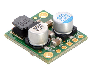
I used the D24V50F 5V, 5A step-down voltage regulator from Pololu to convert to the 5V power required by the electronics. This would accept anywhere from 6V to 38V input power, which handles both the potential voltage drops from transient occurrences like starting the engine, as well as any potential surges. I could have actually used the slightly smaller D24V25F5, which has a max output of 2.5A, but while troubleshooting some issues with undervoltage, I had thought that the regulator power limit might be the culprit and switched to the 5A version, which is only a few dollars more, and has basically the same footprint (and a compatible pin-out).
The Raspberry Pi is somewhat picky about its input power — it actually wants closer to 5.1Vin, and will display a small yellow “lightning bolt” icon on the display if it’s not getting the voltage it wants. If the input is undervolted, the SoC will throttle down the CPU to attempt to draw less power, and will still function down to about 4.7Vin, although there are warnings about unreliable effects at that end of the range.
When I initially wired everything up, I was getting the lightning bolt signal constantly while it was running. My benchtop DC power supply can provide up to 10A at 12V so it was definitely not limited by available supply current. Even after switching to the beefier 5A regulator, that didn’t fix the problem. For a while I mumbled something about capacitance in the breadboard while I was still testing things out and ignored the problem, but once soldered together in the case, I couldn’t put it off much more. I eventually concluded the issue was one of wire gauge; to connect the voltage regulator to the Raspberry Pi’s 5V power pin, I had been using stranded jumper wire from Adafruit that is quite thin (either 26AWG or 28), and this was limiting the current draw. The Pi itself steps down the 5V signal to 3.3V for internal use so it was able to work with this, though it continued to show the warning (and throttle the CPU back to about 800 MHz).
I eventually replaced all the wiring in the power circuit with 22AWG stranded wire and this fixed the problem. (This required crimping my own connectors, but that was straightforward with a $10 crimping tool.) In practice, the amperage throttling due to the wiring gauge must have been very slight but just enough to throw off the Pi’s SoC. With the upgraded wiring, my DC power supply was only showing another 20–40mA current draw at 12V (.25W or so).
Packaging
To really put this together, I needed a case. Polycase has a wide variety of plastic cases in various dimensions, with a number of other available features. For this device, the size of the case would be dictated by the display, which is 6.5″ x 4.1″, plus overhangs for four mounting bosses for screws at the corners. While my MFD has a beautiful edge-to-edge LCD, I couldn’t find a case that offered a particularly tight fit around this form factor. I ended up choosing the Polycase WP-25F, which is 8.74″ x 5.75″. This was for three basic reasons:
- It met NEMA specs for outdoor use in wet environments, rated at IP66.
- It was the tightest IPx6-rated case that fits around the display.
- The “F” edition comes with flanges on either side that would enable mounting at the steering pedestal.
It could also be purchased with the WX-26 internal mounting kit, which provides an aluminum sheet cut to fit inside, that would screw down to internal threaded holes in the case, to which I could mount the PCBs.
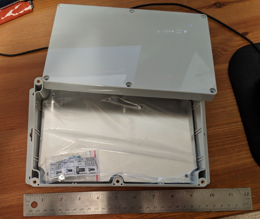
The lid screws down through six threaded holes around the edge, and has a silicone gasket (“ideal for outdoor use in a wide range of adverse conditions”) to help seal along the seam. It feels sturdy, and advertises “durable, impact-resistant UV stabilized Polycarbonate.” The reassurance about UV is also important, since a combo of UV and salt exposure eventually kills everything on a boat.
Even getting down to this size required making some concessions. I was initially hoping to expose connectors for power and NMEA2000, with the NGT-1 mounted internally. But the NGT-1 itself is actually quite large, and would require a 3″ deep case (like the Polycase SG-22); moreover it has several feet of cable on each end (one N2K, the other USB), and those would need to fit somewhere too. By deciding to leave the NGT-1 outside the box and pass a USB connection through, the case could be much more compact.
Connectors
I then needed to pass two connections through this case: one for power, and one for the USB connection to the NGT-1. I needed these to be IPx6 or better as well. Fortunately, DigiKey and Mouser had me covered.
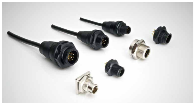
For power, I took inspiration from the B&G MFD I owned already. It had a 4-pin cable with a very sturdy bayonet-locking connection that enclosed the connecting pins very securely. While the cable was sold under the Navico name (parent company of B&G), the cable itself had an “ALTW” logo on the connector overmoulding. Some digging revealed that the cable was manufactured by Amphenol LTW, whose tagline is “unrivaled interconnects for harsh environments.” That seemed like the right prescription to me. However, their catalog of circular connectors is dizzying; running to 50 pages, there are hundreds of SKUs for a variety of pin counts, connector options, max amperage ratings, etc.
It was difficult to decipher exactly which cable and thru-hull connector worked with one another, or mimicked the same style as the MFD. At first, I misread the sheet on how to interpret model numbers, and accidentally purchased a cable and connector that wouldn’t mate. Fortunately, their customer support team was able to help me pick a compatible pair over email. Curiously, I bought the pass-through connector from DigiKey but needed to go to Mouser for the compatible cable. These vendors have variety but not necessarily consistency, it seems.
I wound up with the ABD-04PMMS-LC7001 connector and ABD-04BFFM-LL7A02 cable, which are the same style as the Navico cable, but have considerably thinner-gauge wires, and are 1/3 the price. The Navico cable also has something else custom going on, since their wire colors don’t match the ALTW schematics at all.
If I had to choose again, I’d select a slightly beefier cable. This cable contains 24 AWG wires, which are adequate to provide the power I need, but most crimp terminals are designed for 22 AWG and larger, which made it more difficult to crimp extension wires to the cable’s wiring for the final hookup to power and ground. Sticking with 22 AWG and thicker for external wiring is generally a good idea.
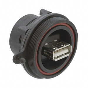
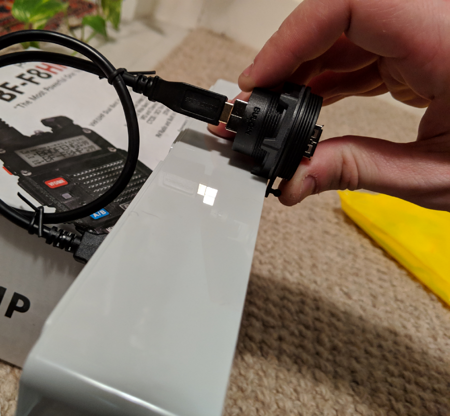
Matt also found a waterproof (IPx7) USB connector that could be used to connect to the NGT-1. You could plug the standard USB-A connector on the NGT-1 directly into it, or use a special companion USB cable that had a plastic shield that would screw onto the ring, over the USB connection itself, to make a water-tight seal. Given that the reach from where I planned to mount the device near the helm was relatively far away from the NMEA2000 bus, I would need a USB extension cable anyway.
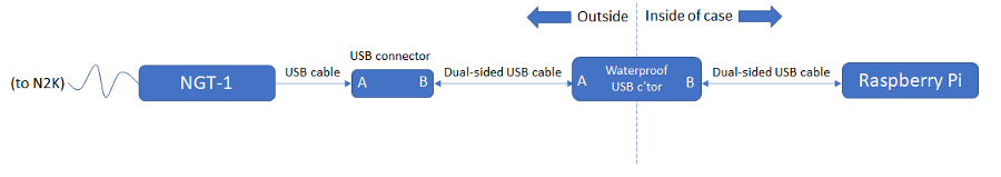
At this point I learned something interesting about USB cables and the USB design in general. While the newer USB-C interface (as used in some smartphones) is symmetric and the devices themselves negotiate host and guest responsibilities, other USB standards are asymmetric and have dedicated “host” and “guest” sides. The “Standard USB” plug you think of when plugging a mouse or keyboard into a PC (USB-A connector) is on the cord attached to a guest device, and the host receives this connector. As such, they don’t make USB A-to-A connectors, since that could let you connect devices in an incorrect hierarchy. The other side of this cable is always a USB “B” connector (the square-ish plug you sometimes see on printers). On the connector shown above, the socket on the rear side (not shown) is a USB-B connector. So the waterproof connector overmoulds a USB-A plug, and the other side of that cable is USB-B. I then have a USB A-to-B connector that lets me plug the NGT-1 into that, which forms a daisy-chain like so:
Adding a waterproof SPST power switch completed the collection. Now I just needed to mount them. I had initially thought I would put them on one of the sides of the case, which would make for a nice set of cables coming out of the bottom when the screen is facing the user, but this wasn’t going to work:
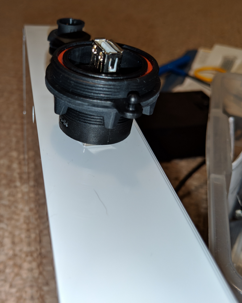
To attach the USB connector there would have required cutting through the gasket and aligning the hole on the case and the sidewall of the lid, which would compromise the waterproof integrity of the whole thing. Time for plan B… go through the back:
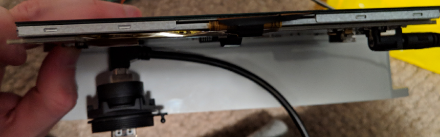
This then quickly demonstrated a separate problem: the USB connector overmould was too tall and wouldn’t fit vertically in the case! I wasn’t looking to buy a deeper case — I felt like this one was already a large enough box.
Fortunately, a variety of alternative USB cables are available; you can buy USB connectors that have an immediate 90° turn before the large plastic element, which solves this problem.
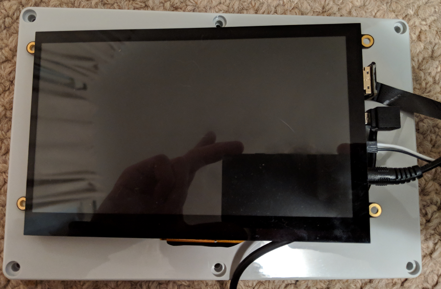
There are similar issues with the display: it does take up most of the lid, so the connectors and strain relief for the HDMI cable and the 2.1mm barrel jack for power would be running up against the right edge. I found 90°-turn versions of these too, including a super flat ribbon cable variant for HDMI rather than the typical bulky wire-bundle cable that has a pretty large minimum turning radius.
Hunting through DigiKey for compatible cables and connectors took a surprising amount of time to do the research. Fortunately I took good notes, so if I do any similar projects in the future, I’ve now got a good collection of starting points.
At this point, I’ve got the main electronics platform with software running on it, a waterproof enclosure, waterproof ports for plugs that will fit in the constraints of the enclosure, as well as internal cable assemblies that also fit. And I’ve also got my power supply figured out. It took a lot of hours of research to get to a solution here. Connector housings can be quite bulky, especially if you plan to use cable assemblies internally; fortunately, you can get cable assemblies without overmoulded plugs or with angled plug options to save on internal space. Even with those in hand, a large portion of the internal volume would be taken up by cable assemblies. Making a thin device is challenging! Requiring IPx6+ waterproof components made the search even more challenging.
But now it’s time to actually put it all together!