
This is the second post in a series about building an embedded electronic device to assist in sailboat racing.
Marine electronics project — table of contents
- Project background
- The platform
- A digression on suppliers…
- The software
- Power and packaging
- Fabrication and assembly
- Mounting and installation (take one)
- Installation (take two) — Success!
To build a device that would accomplish my goals I needed to get the data from the sensor instruments, run some computation over it, and visualize it on a clear display. I needed to choose fundamental building blocks of the system to accomplish these goals.
Electronic marine instruments
For this device to provide accurate information, it must be connected to the other electronic instruments on the boat. My electronic equipment was recently refreshed (in 2018), with gear made by B&G. Other common vendors include Raymarine, Garmin, and Lowrance; all of them have various sensors (boat speed, wind, GPS, etc.) as well as display units. Some displays are single-purpose (e.g., an analog wind direction and speed display) but more commonly you install a “multi-function device” or MFD, which can bring together many different read-outs in an integrated dashboard. MFDs are also commonly called “chartplotters” since they can also usually display a map/chart centered on the boat; the MFD is also usually your GPS sensor and it is also responsible for navigation to waypoints.
On my boat, I have a wind sensor, reporting the apparent wind angle and apparent wind speed; a boatspeed sensor (speed through water); depth sensor; and a Zeus3 MFD which includes a GPS sensor (which in addition to position also reports speed over ground and course over ground).
NMEA2000
Regardless of the vendor, virtually all modern equipment connects together via a standard called NMEA2000 (a.k.a. NMEA2K or N2K), which allows you to mix and match components from different vendors.
(Well, almost. Raymarine uses a proprietary interface called SeaTalkNG which is actually NMEA2000 under the hood data-wise, but uses their own cabling. They do sell adapters to connect with NMEA2000 components though.)
N2K is based on the automotive CAN bus standard. Components are connected on a common bus which implements a many-to-many broadcast serial connection; the N2K connection also delivers power to instruments. Messages are sent as binary data packets, which include a message type id (called a PGN, or parameter group number), length, checksum, some other header fields, and a variable-length, message-type-specific body. There are also standards for how frequently it is expected/acceptable to send each type of message.
CAN specifies several layers including physical connections, power distribution requirements, voltage and timing low-level signaling format, and high-level message format; N2K has its own waterproof physical connectors and cabling (called “DeviceNet”) and its own defined message types and ID numbers (PGNs) for data relevant to marine systems.
For example, messages with PGN 129025 correspond to “position, rapid update” which is sent by a GPS device at up to 10 Hz. The body includes two signed four-byte integer fields that specify latitude and longitude, in increments of 0.0000001 degree.
Building my own device that connected directly to the N2K bus would be a challenging low-level integration, involving reading and driving GPIO pins with precise timing requirements. Even more problematically, N2K is a closed standard and it would be quite expensive to get a copy of the spec. (The full spec costs thousands of dollars, the cheapest useful subset would be $1,800.)
However, a British company called Actisense has made a device called the NGT-1 that converts from an N2K connection on one side to a USB port on the other:
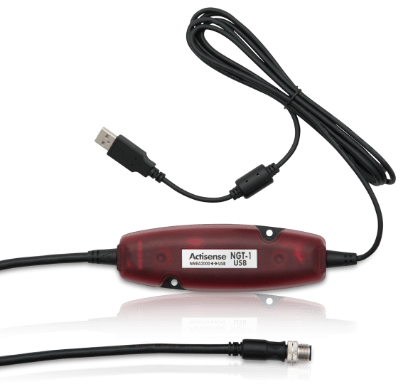
Even better, they have an SDK. This seems like a much faster way to get started (and at $180, about 10x cheaper than even learning NMEA2000, much less implementing it). Finding this device online was one of the sparks for my interest in this project.
What embedded platform to use?
It had been some time since I had last done a hardware hacking project, so I polled some friends and did some reading to choose the basic platform. Things have evolved a lot since I did projects in college on 8-bit microprocessors like the ATMega32!
The two most popular options today are Arduino and Raspberry Pi. My initial requirements list was as follows:
- Data will come from a USB serial device (the NGT-1).
- I need some sort of display, 4–6″. Mostly text, maybe simple graphics if I want to get fancy.
- Support for touchscreen input would be appreciated but I can do without.
- Low amount of field-programmable data. (< 4KB) Could live in EEPROM, doesn’t need a file system.
- Doesn’t require a lot of CPU horsepower, but floating-point support and a math library would make things easier.
- The boat delivers 12V DC power. Sometimes this can dip to 9–10V transiently, e.g. when starting the engine.
- Power to instruments is toggled via a circuit breaker. Ability to support “hard” shutdowns preferred.
- It’s for a boat, so eventually I’ll need to worry about mounting/enclosure for vibration and moisture isolation.
Raspberry Pi has baked-in support for 800×480 HDMI and USB, and a very flexible menu of programming languages, libraries, etc. There are a variety of compatible plug-and-play HDMI+USB touchscreen displays. I’m already quite familiar with Linux programming. It seems like the easiest platform to use.
But it also has a pretty stringent 5V power input, meaning I’d need to integrate a DC-DC power supply. And due to compact flash use, it prefers a “clean” OS-managed shutdown, otherwise the CF card might be corrupted. To be super-safe, I’d also want to integrate a battery or capacitor-based shutdown.
Arduino will operate on 6–20V DC, doesn’t care about losing power the hard way, and doesn’t need to boot an operating system, so it seems like the more rugged choice. But its USB support is more primitive, and managing a screen requires a separate board, more complexity, and would be lower resolution. I’m also limited to C and reduced software library support, so coding would be much trickier.
The cost for either kit is pretty similar so that wasn’t a factor. A friend also clued me into some Raspberry Pi blog and forum posts describing how to mount the microSD compact flash drive in read-only mode, using tmpfs to handle any must-write directories (like /var/log), which would make the power-off issue moot. I could use a separate USB key for persistent field-programmable data (like the targets and polars tables, device configuration settings, or persistent data logging). Between that and finding this cheap and simple 12V to 5V DC/DC regulator from Pololu that would drive up to 5A, I was pretty sold on Raspberry Pi.
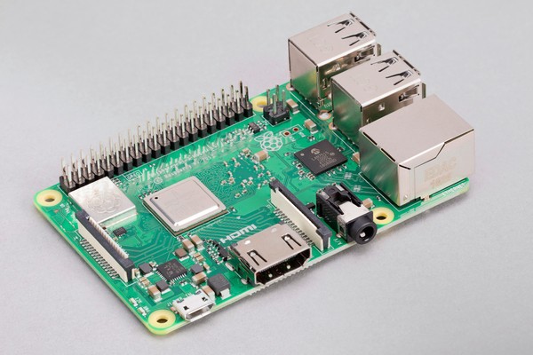
I logged into Adafruit and bought the at-the-time latest model Raspberry Pi 3 B+ ($35). It has 1 GB of RAM; a 1.4 GHz ARMv8 64-bit CPU; wifi, bluetooth and ethernet connectivity; 4 USB ports; compact flash storage (microSD card sold separately); a 40pin header for 3.3V GPIO; and it runs the “Raspbian” port of Debian Linux. The various capabilities listed above are all handled by a Broadcom BCM2837 system-on-chip (SoC). You can install Raspbian by downloading a special image for a USB key which the Pi can boot and then install to the microSD card. An 8GB card is sufficient for a full installation with plenty of room left over for your own code and data.
You can then plug in an HDMI display, USB mouse, and keyboard and use it like any other Linux PC, or SSH in like it’s a server. It is a very slick way to build an embedded hardware system. Raspbian includes packages for everything from low-level Raspberry Pi-specific GPIO control to standard desktop software like LibreOffice and Firefox. It has absolutely tons of computing power and RAM compared to most embedded environments. Most attractive to me was that I could write most of my software using Python, which would be much easier and faster than writing everything in C, and could take advantage of the multitude of Python libraries out there.
The display
As mentioned, Raspberry Pi has native support for full color HDMI in 800×480 resolution, which is a lot of screen real estate to work with. There are also a lot of small HDMI-compatible touchscreens available; they can be plugged into the Pi’s USB port to emulate a mouse. Adafruit has a variety of displays available to browse through; a 5″ LCD touchscreen is only $75!
Unfortunately, I had another complicating requirement: it needs to work outdoors. Lower-powered LCDs will appear faded and unreadable in bright sunlight, so those wouldn’t fly. Instead, I purchased a 7″ sunlight-readable HDMI touchscreen display from Newhaven Display (model NHD-7.0-HDMI-N-RSXN-CTU). At $116, this would be the priciest item on the BOM besides the NGT-1 ($180); but it’s a high quality pro-grade component with a detailed integration guide. (And, whether due to the current chip shortage or simply because it’s popular, at the time of this writing that price is now up to $187! I was very careful to treat the display gently and not break it…)
This display is beautiful, but as we’ll talk about later when we get to integrating everything in a case, mounting the display would become one of the most cumbersome aspects of the project — something I didn’t really expect up front!
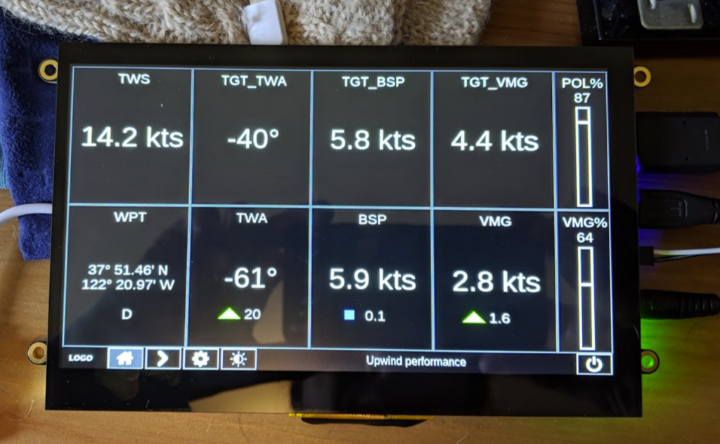
I was actually hoping for a more compact setup with a 5″ touchscreen, but 7″ was the smallest I could find that’s sunlight readable; if you need an LCD you can read in full sun, your options are quite constrained. But the larger size did enable me to design a very legible and uncrowded screen, as well as do some fancier graphing that would have been hard to read on a small display.
Another minor “gotcha” issue with this display is that there’s a flexible printed circuit sticking out of the bottom that wraps back underneath the device (you can see it in the photo of the powered-on display up above; a small black and gold tab on the bottom of the device). If anything makes contact with that FPC, the touch-control doesn’t work. I figured that out by trial and error; sometimes the touchscreen wouldn’t respond, and I eventually identified that as the cause. When working with the unmounted display on my desk I eventually learned to make a “tray” by placing two paperback books on my desk with a gap between them a bit wider than the FPC, and resting the display across the books.